Folks:
Can anyone offer guidance on the Q105/Q106 matching problem I noted in post #274? If anyone knows of a source for matched transistor pairs (ideally for <65V) or can explain whether there is a way to compensate for a mismatch (in my case, hFEs of 215 and 309), I would be very grateful.
Thank you!
Can anyone offer guidance on the Q105/Q106 matching problem I noted in post #274? If anyone knows of a source for matched transistor pairs (ideally for <65V) or can explain whether there is a way to compensate for a mismatch (in my case, hFEs of 215 and 309), I would be very grateful.
Thank you!
@SRMcGee, sorry that your post was missed. Mismatched devices will still work OK but the THD could be degraded a little. Super results were obtained during testing with tight matching but the design effort put into this circuit is so refined that the difference will not necessarily be noticeable. TTA/TTB are superior for their frequency response as well remember so I would be happy to go forward with those that you have. And given the supply constraints seen these days I am not sure you could do any better.Folks:
Can anyone offer guidance on the Q105/Q106 matching problem I noted in post #274? If anyone knows of a source for matched transistor pairs (ideally for <65V) or can explain whether there is a way to compensate for a mismatch (in my case, hFEs of 215 and 309), I would be very grateful.
Thank you!
Hi guys, can someone of you, please, write definitely a list of the transistors pairs that from the schematics need to be matched? Build guide only recommends to match Q1-Q2 and Q3-Q4, but I see that there are also other pairs which need to be matched to achieve the best results in terms of lower THD. So I think that it could be better for all to know exactly which pairs we should try to match. Thank you.
Gaetano.
Gaetano.
Thanks Johno,@janusz, I suspect I will regret trying to answer this one....but here goes:
My understanding is that a class AB, emitter follower, SS, feedback amp is a voltage source having essentially zero source impedance and a meaningless infinite damping factor.
Also that Tube amps with an output transformer on the other hand have an output impedance designed to match the speaker impedance to achieve maximal power transfer, which of course is where and why damping factor became a thing. Possibly a class A, no feedback amp with an output capacitor also has significant source impedance and would need to consider load matching. Because speaker impedance changes with frequency (eg drops at woofer resonance) the amount of power "lost" in high source impedance amps also changes and typically this is most noticeable at the low frequencies approaching woofer resonance.
These days I see DF as a marketing thing of no consequence unless you have transformer outputs.
when I build it I'll measure DF by measuring internal output impedance R = Rload (Vopen/Vload -1) first at say 1kHz or 100Hz
Maybe somebody will measure it well before me as I don't think I'll have it before early August and will post it here.
cheers,
Q1/Q2 and Q3/Q4 are the only critical pairs.Hi guys, can someone of you, please, write definitely a list of the transistors pairs that from the schematics need to be matched? Build guide only recommends to match Q1-Q2 and Q3-Q4, but I see that there are also other pairs which need to be matched to achieve the best results in terms of lower THD. So I think that it could be better for all to know exactly which pairs we should try to match. Thank you.
Gaetano.
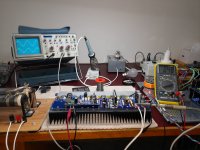
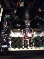
Second board passed its prelim tests, bolted to my test bed heatsink and amplifies a signal into my dummy load (after all the adjustments etc). Ran it for 30 minutes with the 72V rails at about 5 watts, bias stabilised nicely, all heatsinks barely warm. Took it to 100W for 10 minutes and all OK. Tomorrow do the same with the other board. Run both boards for a day to be sure, then de-commission the HB boards, drill and tap the 5U heatsink to suit and squeeze it in somehow amongst the preamp etc, protection SSRs, softstart and power supplies. Some photos, because...


Attachments
Johno:@SRMcGee, sorry that your post was missed. Mismatched devices will still work OK but the THD could be degraded a little. Super results were obtained during testing with tight matching but the design effort put into this circuit is so refined that the difference will not necessarily be noticeable. TTA/TTB are superior for their frequency response as well remember so I would be happy to go forward with those that you have. And given the supply constraints seen these days I am not sure you could do any better.
Thank you! Your explanation puts my anxiety at ease. If we ever emerge from the supply constraints that have been plaguing us for the past couple of years I may tear this amp open and replace those transistors with matched sets, but it's good to know that this project can proceed in the meantime.
Much appreciated,
Scott
Folks:
I'm still waiting for a few key parts to arrive, but significant progress has been made on my integrated Wolverine amplifier project. Antek is supplying a custom 500VA toroid (two 35V and two 13V secondaries), I have to build a simple board to handle the knob backlight and selected source LEDs and the attenuator has to be mounted, but it does appear as though everything will fit in this gorgeous HiFi2000 3U chassis. Nothing has been tested so far, either (expect a few panic posts on that front), but things are looking good from my perspective.
Kudos, once again, to the Wolverine Design Team and Gianluca and his cohorts at HiFi2000!
Regards,
Scott
Attachments
Last edited:
Finally got this thing together 🐱. Ended up a little more cramped than intended as I got the transformers for a good price and couldn't pass on them. It's dead quiet despite the proximity to the PCB. Definitely an upgrade over my lm3886 amp ... Thank you to everyone for the help and inspiration to build it. ")
Attachments
Hi All,
I missed the notifications of a few posts on this thread, so I have just caught up.
It is really great to see a lot of Wolverine builds happening !!!
Also here is a link to the sine wave testing YouTube video I did recently, I dont think I have posted it in the build thread, my apologies....
The winner of the green PCBs is announced in the video, also I took the amp to full power at 8 Ohm, 4 Ohm, and 2 Ohm loads with unregulated 57 Vdc rails and a 1 kVA transformer on a single channel for those of you who are interested.
Enjoy:
Hi Guys,
I received the first review of the Wolverine amplifier by @fireanimal. He was not part of the design team
and has had no direct contact from any of the design team members during his build.
So I believe his review is unbiased.
I would like to thank @fireanimal for the time he has taken to write this detailed review.
Hopefully this will encourage other members to build the Wolverine.
I will add his review to the first post of this Thread so new members can read it before they begin this journey.
If anyone else would like to write a review, I will add theirs as well.
Attachments
Single microaudio cobra-s2 SMPS@fireanimal are you using a single psu or dual mono in your builds?
Cobra S2
Hi Guy's
Just uploaded another small build guide update to the wolverine project Dropbox.
The current revision is now Rev 21 - 30/06/2022
Updates are listed at the end of the file as always
Thank you to @fireanimal and @miran50 for their input.
Just uploaded another small build guide update to the wolverine project Dropbox.
The current revision is now Rev 21 - 30/06/2022
Updates are listed at the end of the file as always
Thank you to @fireanimal and @miran50 for their input.
Finally getting ready to order parts! I have a couple transistor questions-
1) For those that built the jig to really accurately match transistors - would you consider selling me matched pairs for Q1, Q2, Q3, Q4? I would appreciate having ones that are matched as closely as possible and I don't have the means to.
2) Just to confirm- here is what I am thinking for transistors. Planning a beefy build that can handle 4ohms, first build will be 60v, but I'd like to keep the door open to upping that to 70v in the future.
Predrivers KSC3503E KSA1381E
Drivers MJE15032 MJE15033
Outputs MJL3281 MJL1302
Look okay? Since they are due back in stock soon and not too much more I may do MJL4281 MJL4302 for the outputs. Sorry I really don't understa
Thanks, Mike
The larger number gives a better chance and I have tended to get lots of 100 if its a good price break. But it depends on your budget I guess.Hello,
Are Q1, Q2, Q3 and Q4 the only devices that need to be matched (other than the resistors noted in the build guide)?
What quantity of each is it suggested to by to find a reasonable match?
Thanks,
Alan
Finally getting ready to order parts! I have a couple transistor questions-
1) For those that built the jig to really accurately match transistors - would you consider selling me matched pairs for Q1, Q2, Q3, Q4? I would appreciate having ones that are matched as closely as possible and I don't have the means to.
2) Just to confirm- here is what I am thinking for transistors. Planning a beefy build that can handle 4ohms, first build will be 60v, but I'd like to keep the door open to upping that to 70v in the future.
Predrivers KSC3503E KSA1381E
Drivers MJE15032 MJE15033
Outputs MJL3281 MJL1302
Look okay? Since they are due back in stock soon and not too much more I may do MJL4281 MJL4302 for the outputs. Sorry I really don't understa
Thanks, Mike
Those choices are good and MJE15034/35 with MJL4's slightly better performance and Safe Operating Area for 71Vdc supplies
- Home
- Amplifiers
- Solid State
- DIY Class A/B Amp The "Wolverine" build thread