Yes, it's a diy product, not a clear market regulation product. In diy, one is entitled to his own desires. And it is much much safer than putting a copper rod in fuse holder as many would do with such a device, as you said it yourself "audiophiles that notice blacker than black backgrounds" and may i add "purists".
So everything can be allowed? It is not about personal desires at all. It as about a design that can create severe overcurrents when there is overvoltage. It MUST be fused due to design choices.
Tell that to the people that remove every bit of protection from commercial devices because it sounds better to them (i personally know i few, and from a very very expensive equipment, even opting for thick solid core wire replacement on pcb, even though the device being transported...). For those people it is much safer to use as is, rather than put a stick of copper in the fuse holder (which i've also seen personally). Don't get me wrong, this device is made for a specific purpose, and as such it needs to have protection, but experience is, people are dumb 🙂 And choosing a lesser evil is usually the correct path. You know that you cannot force people, what you can do is make it less dangerous for dumb decisions.
Well then, let's go back to the beginning. Take a look at the OP schematic. Other than the fuses, what other thing did you need to adjust? At this point it would be easier for me to do a new PCB all together than editing the existing jpg picture of the bottom layer.
Well, I looked and think this device should not be built at all in its current form as it interrupts PE by means of L3 and R1 in parallel. This is against code. The ground loop breaker should be in a device it feeds and then from Audio GND to PE. The way it is now also means that the shielding is “lifted” which can not be allowed as the shielding can possibly be touched. The situation around the GDT and RV1 and RV1 and that of R2/R8 and C3/C10 is plain bizarre and already concluded in post 16. They of course won’t be a problem as they will never see action 🙂 Resistors F1 and F2 (fusible?) limit current when the MOV triggers but why? Normally one wants the MOV to clamp and let the fuse blow ASAP to protect the load. Also it would be good, besides the fuse, to use the correct terms L, N, PE and 230V.
Sorry. Just think what the situation is when connecting a 3 prong amplifier to this device. The amplifier casing will not be connected to PE but via a 6A maximum coil in parallel to a 20 Ohm resistor.
Sorry. Just think what the situation is when connecting a 3 prong amplifier to this device. The amplifier casing will not be connected to PE but via a 6A maximum coil in parallel to a 20 Ohm resistor.
Last edited:

You're making me laugh., sorry.I just need permission from the OP to share the files, since from what I understood he is selling the circuit himself? What do you think?

I asked for something that's related to your work and not someone else's. I don't think anyone is competing commercially with someone else.
It's for personal use and possibly a few friends. I don't want to get rich off this project.
I'll let others do that.
I also made PCB variants for diyaudio's commercial projects and no one had anything against it.
The files are already posted on the forum, freely.
Yes please! I'm currently going through some exams session at uni and I don't have much time for that at the moment.
Ah yes yes, I agree. I thought you talked about the project file I sent.
You would need to start from scratch, as I said the file there is just the image provided by the OP converted in vector and applied to the copper layers.
Quick and easy method to make a PCB from any magazine or scan, but prevents edits on the base layer, so the source must be reputable and correct from the very beginning. Here's an example of how it turns out
Hi, I have seen a lot of commercial EMI Filters like from Schaffner the E types which have a Choke in the PE line, and then I remembered from my education 20 years ago that PE is not allowed to be broken as you mentioned. Hmm can you clarify this for me. Maybe choke is allowed? Sorry it's a question, not smart as talk 🙂Well, I looked and think this device should not be built at all in its current form as it interrupts PE by means of L3 and R1 in parallel. This is against code. The ground loop breaker should be in a device it feeds and then from Audio GND to PE. The way it is now also means that the shielding is “lifted” which can not be allowed as the shielding can possibly be touched. The situation around the GDT and RV1 and RV1 and that of R2/R8 and C3/C10 is plain bizarre and already concluded in post 16. They of course won’t be a problem as they will never see action 🙂 Resistors F1 and F2 (fusible?) limit current when the MOV triggers but why? Normally one wants the MOV to clamp and let the fuse blow ASAP to protect the load. Also it would be good, besides the fuse, to use the correct terms L, N, PE and 230V.
Sorry. Just think what the situation is when connecting a 3 prong amplifier to this device. The amplifier casing will not be connected to PE but via a 6A maximum coil in parallel to a 20 Ohm resistor.

A choke in N is possible. Never saw one in PE (till now). PE should not be interrupted.
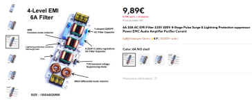
Something cool could also be rebuild the filter around these chokes and inductors, they're easily available on the internet. You could even buy that filter, harvest the components from it and use them for the filter If needed, making the new board around those components. 👌I just stumbled upon this, maybe some of the elements here can be taken into consideration for modifying the circuit, like the connection of the GDT. This version has also a fuse.
- Home
- Amplifiers
- Power Supplies
- DIY EMI filter for power supply