Is supporting a corrugated membrane on the long side really a good idea? I mean, that bend that is needed to move the membrane is really opposite of what the corrugation is trying to mitigate, no?
I think so. The corrugations will stiffen the the membrane from side to side which is what I want.
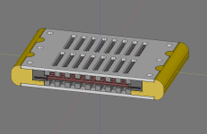
This of course requires that the gasket must be really soft and squishy since it needs to account for the movement. I assume I will print it in 55A shore hardness with thin walls and pretty low % of infill. Something like this:
And I plan to use 1.5 mm carbon steel, and only if it proves to be too weak go to 2mm.
And the threaded inserts will of couse be a weak part but I don't think they need to be that strong . They just have to be strong enough such that I can mount the driver first rear then front instead of having to add both the front and rear steel sheets + magnets at the same time. When the front is mounted and screwed with screws and nuts then I will be able to unscrew the middle screw into the insert since it will not be as strong as the outer 2 screws + nuts.
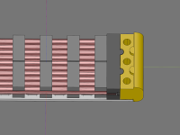
But you are correct that I might need to think more of how I can mount the front without gambling to destroy the membrane since the magnets will be strong. My dad had a great idea that I could use long non magnetic axle steel rods to help guide the front plates:
- Mount the rear plate into the side with a small weak screw (blue) into the threaded insert.
- Add membrane + gasket
- Use long stainless non magnetic axle steel rods to guide the front plate with magnets down such that it locks in the indexed pegs. Then replace 1 rod with a screw (red) and nut untill all rods are replaced. Then repeat for each front steel plate.
- Remove the now redundant weak blue screws into the threaded insert.
I have ordered from Aliexpress, so remains to be seen if they are actually 50x3x3 mm...Where to get magnets like 50x3x3 mm?
Attachments
Sounds like a great plan, OllBoll.
I'm still worried though that the threaded inserts will not be strong enough when you mount the front plate.
The mounting "red" screws might also be too short, perhaps you should start with longer ones?
I'm currently using two mm carbon steel.
It failed when I tried nine columns of magnets, the plate bulged one mm in the middle, so now I will try five columns as you have.
I will post the result in my current thread.
I'm still worried though that the threaded inserts will not be strong enough when you mount the front plate.
The mounting "red" screws might also be too short, perhaps you should start with longer ones?
The front plates won't be mounted in the threaded inserts. Only the middle blue screw will go into a threaded insert which temporarily mounts the rear plates to the edges.
And yeah, the red screws which will be what actually holds everything together will probably be longer.
And about the thickness yeah. Note that my current models are a lot shorter than yours. My have 40 mm width with holes where yours has 80 mm. And across the magnet gaps I have a lot more steel supports. I have 24% supports where yours has 5%.
The temporary screw insert must still be able to hold back the repulsive force of the magnets
Hmm, you are right.
It might be stronger if I ues a short 3 mm insert but inserted from the top. It would add more material and make the insert act more as a nut glued in place.
Attachments
Or use a nut?
...
I'm still a little concerned about the inserts. Do you have a tool to get them correctly inserted?
Only using a soldering iron can be a little tricky.
I'm hesitant to use nuts because then I have to ensure they are all screwed in tight or I will risk having them rattle. Or I will have to glue them in but what if I am uneven in my glue application so they rattle anyway? Or maybe I mess up and accidentally put glue in the threads which is annoying to deal with.
All in all while heatserts are more expensive than nuts they are extremely convenient to use, so I will probably use them unless I can figure out another more simple way to temporarily connect the bottom to the edges than with a heatsert.
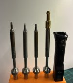
I use specialized soldering tips. At first I had to make my own since there wasn't off the shelf tips available for my iron (TS101) but now I use these.
The third tip from the left is my custom made m3 tip and the rightmost is the m3 tip of the set I linked with a short m3 heatsert on top.
They are really easy to use and align. I tried first to just use a normal iron but like you said it is really tricky to get them in straight without tilting them just enough to mess things up. With a specialized tip that wasn't a problem anymore, alignment is really easy since the tip is cylindrical so makes contact with the heatsert both on the top and bottom so as long as the iron is centred an aligned correctly then the heatsert will be. And in the odd case where it isn't it is easy to reheat the heatsert and just tilt it back into alignment.
Attachments
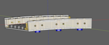
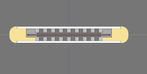
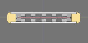
I've been thinking of simplifying the edge:
Since I'm building a dipole I want to ensure that the baffle width is small enough relative to the radiating width to ensure that I don't get a big dipole peak null in my frequency response.
I believe I should have no issues as long as the radiating width is not less than 50% of the total driver width, based on that the Neo3W which performs great and has no dipole peak has exactly 50%. (33.8 mm radiating width, 67.5 mm total width).
My latest model had 40 mm radiating width and 73 mm total width including the steel edge plates. My thought is that I can probably widen that to 80 mm without impacting the performance and with 5 mm more solid material on each side I can probably skip the edge steel plate altogether since it should be stiff enough without it. I can also add a nice rounding which should make it even better.
Attachments
Last edited:
Yes, Stefan knows what he is doing. Perhaps I will buy one adapter as well then and also the TS101. It can come in handy when soldering the aluminium strips since the tip's temperature can be controlled.
Nice touch with the rounded plastic edges! (I might steal that.)
Make sure that the joints between these are in the middle of the steel plate.
Otherwise you'll have weak spot between the plates.
Nice touch with the rounded plastic edges! (I might steal that.)
Make sure that the joints between these are in the middle of the steel plate.
Otherwise you'll have weak spot between the plates.
Last edited:
The suspension... will it be linear and have the right compliance.... I think it will be hard to accomplish... but I hope so and if you are in the capital I would very much like to audition these when finished is possible pleaseI think so. The corrugations will stiffen the the membrane from side to side which is what I want.
")
//
The suspension... will it be linear and have the right compliance.... I think it will be hard to accomplish... but I hope so and if you are in the capital I would very much like to audition these when finished is possible please
Yep, the suspension is the part where I am the least confident. I hope I will be able to get it good enough in the end. But I think I will need to iterate at least a few times until I get there.
And yes I live in the capital so when they are finished you are welcome
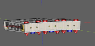
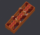
I got my first batch of N35 magnets from Aliexpress today. They were the cheapest ones I've ordered and I was right that the 50x3x3 mm dimensions were guidelines rather than true specificaiton. In practice they are 48x2.6x2x6 mm. All the magnets in the batch are the same so I can just work around it by going with 9 rows of magnets instead of 7.
I have more hope that the supposed N52 magnets I ordered (12x5x3 and 12x4x3) will have the correct size since the seller for them posted pictures with calipers. But they should arrive in a week or so and then I will see.
I have decided to hold off ordering the laser cut steel parts until i get N52 magnets and can measure them since they are the ones I am most likely to actually use.
Attachments
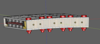
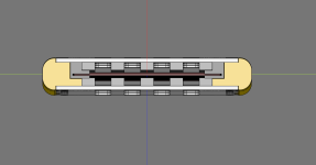
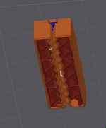
I did some more modeling of the gasket and having it overlap under the magnets is probably a really bad idea. It would limit xmax by a lot.
So I have changed the gasket to be symmetric up / down and get indexed into the side with small cylinders instead of to the bottom.
I also played around some in my slicer to to see infill and such. I think that would work but I would want to test different infill patterns and infill percentages. I rendered first with my 0.6 mm nozzle but it didn't look too good, I think I will need to swap back to my 0.4 mm nozzle when printing these parts.
The question is how much the membrane needs to overlap the gasket though. In these models there is roughly 4 mm on each side which isn't that much. I might need to widen the gaskets to at least 5-6 mm on each side but since all those parts are printable it should be easy to print lots of combinations and then try them one after another.
Attachments
Last edited:
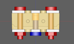
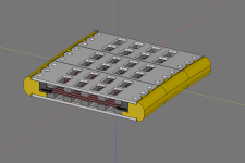
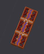
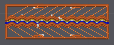
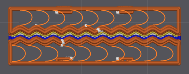
Probably a good idea to disconnect the index pegs such that they don't impact the suspension.
It is probably a good idea too to remove the infill completely in the slicer and instead add the infill lines to the CAD model. That would also let me ensure the suspension is equal over the whole length and not dependent on printing direction or position.
It would also enable me to get creative, the most simple is probably to just have straight lines that do not cross. But I I wanted to I could twist the lines which I think would let it move with less resistance.
Although the most common suspension geometry seems to be a half circle and I don't think they choose it just because it looks nice. Probably worth trying.
Attachments
Last edited:
- Home
- Loudspeakers
- Planars & Exotics
- DIY midtweeter planar, physically curved and shaded to be used in a dipole CBT