I'm not sure what you are measuring, I'll need more details.
Amp or preamp?
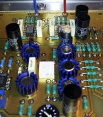
Biasing the amp is pretty straightforward. There are drain resistors associated with each fet. The FETs are interleaved for thermal balancing. The voltage across any pair should average to around 100 mV. If they are close don't touch them. The heatsink will be pretty warm normally. The bias pot is the single turn pot. Be very careful because you can make a lot of smoke fast.
The offset pot is the rectangular pot. Short the input and adjust that until the heatsink (which is at output potential) is at 0 +/- 10 mV and let it stabilize.
The preamp is similar. I think the info is in the preamp manual. Which version of the preamp do you have?
Amp or preamp?
Biasing the amp is pretty straightforward. There are drain resistors associated with each fet. The FETs are interleaved for thermal balancing. The voltage across any pair should average to around 100 mV. If they are close don't touch them. The heatsink will be pretty warm normally. The bias pot is the single turn pot. Be very careful because you can make a lot of smoke fast.
The offset pot is the rectangular pot. Short the input and adjust that until the heatsink (which is at output potential) is at 0 +/- 10 mV and let it stabilize.
The preamp is similar. I think the info is in the preamp manual. Which version of the preamp do you have?
Spectral amps & MIT cables
MIT has a diy speaker cable including the required networks that will work with the Spectral componant.
Audiogon also has a lot of options of used cables that will work with the Spectral gear.I believe any MIT networked cable,speaker or i/c will work.
MIT has a diy speaker cable including the required networks that will work with the Spectral componant.
Audiogon also has a lot of options of used cables that will work with the Spectral gear.I believe any MIT networked cable,speaker or i/c will work.
thanks again demian.
i was talking about the amp. the pre has not arrived yet (first one fell through, and the second has still not been shipped). it's a dmc-10 delta. i did find a manual online, but assume it was for the original (non-delta) if that matters. it seemed to have bias instructions and how to set the gain, etc. included.
also, i'm uploading a photo to make sure i know what to measure. i have marked some resistors w/ yellow dots. are they the drain resistors? and are the pots the ones right next to the output transistors under the wires?
i can only find one set of rectangular pots and they are on the sub-board that is mounted at a 90 degree angle to the main board. are they the correct ones to adjust for offset? and when you say measure the voltage at the heatsink, in relation to what? ground?
thanks a lot for your help, and sorry for all the questions!
one final question, would you advise replacing the electrolytic caps? at 25 years old, are they most likely on their last leg?
btw, i can take any other photos if necessary to make sure i'm measuring and adjusting the appropriate components.
here is a link to the photo:
http://www.kokyu.com/clients/dma50.jpg
Re: Spectral amps & MIT cables
thanks for the heads up. i had no idea they were offering diy options now. although when you add all the networks in, it's still a $1200 pair of cables! but it is cool that they are offering it.
thanks for the heads up. i had no idea they were offering diy options now. although when you add all the networks in, it's still a $1200 pair of cables! but it is cool that they are offering it.
2excel said:MIT has a diy speaker cable including the required networks that will work with the Spectral componant.
Audiogon also has a lot of options of used cables that will work with the Spectral gear.I believe any MIT networked cable,speaker or i/c will work.


I have a DMC-10 Gamma that has some swollen caps and one that has the top broken off. I would like to replace them all if possible but it looks as though it will be difficult to remove the circuit board. The caps all appear to be 35uf 50VDC. The preamp works but the power LED is dim and it doesn't seem to sound as good as it did years ago(it has been in storage) Any suggestions?
The whole circuit board comes out pretty easily. On the rear there are two allen head screws near the bottom. Remove the top and those two screws. Then the board slides out the back.
Replacing all the electrolytics at its vintage is a good idea. Use good 50V caps. The largest value that will fit in the space. You will need a big iron. The ground plane is very heavy.
Replacing all the electrolytics at its vintage is a good idea. Use good 50V caps. The largest value that will fit in the space. You will need a big iron. The ground plane is very heavy.
Thanks Demian. I've been looking around for a replacement cap but they seem hard to find. The old ones appear to have a paper dielectric. Won't the new caps be smaller in size?
Attachments


Anyone have a schematic of the amp (50) they want to share?
You can send a PM if you don't want to post it
Regards
David
You can send a PM if you don't want to post it
Regards
David
Attachments

Demian, The caps are 35uf 50VDC. Shouldn't I use the same value with a higher voltage rating? And are they in the signal path? Should they be audiophile grade or are they power supply caps? Should I use something besides electrolytics?
No. Sorry.
I only have the DMC-10 because it is the phono loading schematic from the owner's manual.
That's the component placement drawing, not the schematic. There is a simplified schematic in the early version of the manual.
The caps are all in power supply locations. The caps were the largest low esr caps available in the late 1970's. This would be a good choice: EEU-FM1H181L Panasonic Electronic Components | P12396-ND | DigiKey Do confirm the fit and the lead spacing. Its similar to what I have used in previous upgrades. The big cap bank is really hard to remove so don't unless you see evidence that you need to.
Most electrolytic caps have paper inside saturated with the dielectric fluid in my experience.
The DMA 50 is very similar in circuitry. What do you need to know about it?
I do not have the schematics but I can replicate them from memory if really necessary.
Last edited:
No. Sorry.
That's the component placement drawing, not the schematic. There is a simplified schematic in the early version of the manual.
The caps are all in power supply locations. The caps were the largest low esr caps available in the late 1970's. This would be a good choice: EEU-FM1H181L Panasonic Electronic Components | P12396-ND | DigiKey Do confirm the fit and the lead spacing. Its similar to what I have used in previous upgrades. The big cap bank is really hard to remove so don't unless you see evidence that you need to.
Most electrolytic caps have paper inside saturated with the dielectric fluid in my experience.
The DMA 50 is very similar in circuitry. What do you need to know about it?
I do not have the schematics but I can replicate them from memory if really necessary.
Is there anything within reason I could do to improve the sound quality of the preamp? Would it be difficult to change out the volume control or even add remote controlled volume?
This is somewhat of a cross-post, since rwwear started a thread with the same preamp questions here: http://www.diyaudio.com/forums/solid-state/273391-spectral-dmc-10-repair-help.html#post4302968
suggest this is likely contrary to the "rules" here... since you've been here since 2005, that ought to make sense??
I just happened to recognize the thread topic and clicked on it, was surprised as a result.
suggest this is likely contrary to the "rules" here... since you've been here since 2005, that ought to make sense??
I just happened to recognize the thread topic and clicked on it, was surprised as a result.
- Status
- Not open for further replies.
- Home
- Amplifiers
- Solid State
- DIY option for spectral amps?