Link that 11mm ... is it SIP/female? Do you use the 6 or 8 pin ?
I was thinking of sourcing a "board stacker" - DW-07-07-T-D-200 Samtec | Mouser
to get my desired height.
(Below) is the current 4'th final ... haha ! PCB.
I was thinking that one could have the onboard wolverine fully populated ,
have enough clearance to just plug in a Spooky or whatever right on top.
Either a standalone project (wolverine) with modular capability OR just
a OPS/regulator "devious playground" for IPS's.
OS
Hi OS, Is there any chance that you can change the Faston connector macro to this one. It supports both the Faston connector and a single terminal screw.
I personally find the single terminal screw is a more positive and secure connection.
I've included the sprint layout macro in the attached zip file.
What about fuses, I don't see any rail fuses. These may work?
732-11372-ND
732-11378-ND
I also made a small trace modification suggestion to try and keep the input ground trace a clean as possible. By making this modification it will keep the return currents from R15 away from the input ground trace.
Is it possible to label the schematic shown in your first post with the corresponding ground points. This will save the confusion that went on in the HB thread.
Eg... G1, G2 etc...
Should the ground that R102 and R103 are connected to be labeled G3?
What about Test points for Bias etc?
I don't see RLift on the schematic
Attachments
Last edited:
Isn't the FC frequency and the input filter a completely separate thing.At what fc frequencies do you set your input filters at?
The HB low pass filter is about 720khz
This SOB looks to be about 2Mhz
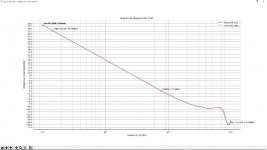
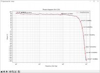
The stock FC frequency (unity gain crossover frequency) of the HB measured 780Khz without the C2 capacitor in place.
I also added the bode plots showing the frequency response with C2 in place.
View attachment 938434


View attachment 938445View attachment 938446
Last edited:
Hi OS, Is there any chance that you can change the Faston connector macro to this one. It supports both the Faston connector and a single terminal screw.
I personally find the single terminal screw is a more positive and secure connection.
1. What about fuses, I don't see any rail fuses.
2. I also made a small trace modification suggestion to try and keep the input ground trace a clean as possible. By making this modification it will keep the return currents from R15 away from the input ground trace.
3. Is it possible to label the schematic shown in your first post with the corresponding ground points. This will save the confusion that went on in the HB thread.
Eg... G1, G2 etc...
4. Should the ground that R102 and R103 are connected to be labeled G3?
5. What about Test points for Bias etc?
6. I don't see RLift on the schematic
1 . I think these are better left to the chassis or power supply cap board. Some might want MOSFET rail protectors (21st century).
2. Good call - done ! R15/R17 do not really contribute substantial return currents. But , why not.
3/4 . G1 is the main "dirty star". G2 at the regulators is still slightly "dirty",
return currents of C102/3 , C106/7 are there , 20db down from G1.
G2 on the IPS IS correct , it is on the same star as the OPS G2.
5. SIP 1 allows testing of the first P/N pair's Re. Also allows hookup of
overload monitoring. DC could also be detected there.
6. I'm still waiting for Thimios's report on Spooky servo behavior in regards
to what IPS ground references get lifted.
Thanks for those connector pads.
OS
Isn't the FC frequency and the input filter a completely separate thing.
The HB low pass filter is about 720khz
This SOB looks to be about 2Mhz
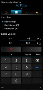
R2=27k C2=100pF so , fc= 1/(2 pi RC) So .....it's a 58.97Khz /-3db 1st order
filter.
The amp itself (you are spot on) WITH two pole is 1.93 Mhz ! (below 1).
If I build mine , I will go with just normal 68pF miller comp. (below 2).
Still , 1.2Mhz ... but I like the phase margin.
The extra 20db gain at LF with TMC halves THD.
Ahh , I know where I got that 150Khz figure 22k/47pf = 153Khz
That is what is on some of my early sims.
OS
Attachments
Last edited:
That adjustable mezzanine connector looks neat! Is it meant to plug in or solder both ends?
Adafruit sells a header kit for the Arduinos that would work here too. I think there's an 8 pin one in the kit. https://www.mouser.ca/ProductDetail/Adafruit/3883?qs=/ha2pyFaduidPXPXSuFTA%2B17jDyV9poj5YQY8EXFvtY=
Originally meant to solder both ends , but .... it could provide height to allow for a low profile female to be used on one of the ends.
OS
1 . I think these are better left to the chassis or power supply cap board. Some might want MOSFET rail protectors (21st century).
2. Good call - done ! R15/R17 do not really contribute substantial return currents. But , why not.
3/4 . G1 is the main "dirty star". G2 at the regulators is still slightly "dirty",
return currents of C102/3 , C106/7 are there , 20db down from G1.
G2 on the IPS IS correct , it is on the same star as the OPS G2.
5. SIP 1 allows testing of the first P/N pair's Re. Also allows hookup of
overload monitoring. DC could also be detected there.
6. I'm still waiting for Thimios's report on Spooky servo behavior in regards
to what IPS ground references get lifted.
Thanks for those connector pads.
OS
I will try to recall this old story. 🙂
2. Good call - done ! R15/R17 do not really contribute substantial return currents. But , why not.
OS
And if You substitute R15 and R17 with single resistor, and avoid ground connection?
The screw terminals mentioned by Stuartmp are very nice, and allow tight connection. I use them long time ago for all DC psu related connection.
R2=27k C2=100pF so , fc= 1/(2 pi RC) So .....it's a 58.97Khz /-3db 1st order
filter.
The amp itself (you are spot on) WITH two pole is 1.93 Mhz ! (below 1).
If I build mine , I will go with just normal 68pF miller comp. (below 2).
Still , 1.2Mhz ... but I like the phase margin.
The extra 20db gain at LF with TMC halves THD.
Ahh , I know where I got that 150Khz figure 22k/47pf = 153Khz
That is what is on some of my early sims.
OS
Its R1/C2 not R2/C2, this gives a high fc, so was just wandering if its intentional.
I use fc as a generic term for -3dB cut off frequency of the filter.
Regards
What are the preferred OPAMPs for the servo? I see Apexaudio in the forum use LF411, im guessing it's for its high slew rate 13V/us. I'm not sure what to look when selecting a servo opamp.
Regards
Regards
LF411 is not a bad choice. Input offset is less than 1 mV. TL051/2, TL031/2, OPAx131 are a few others.
Slew rate doesn't matter. Noise matters some. Offset matters the most. You generally want JFET or CMOS input so that input bias current is negligible.
Slew rate doesn't matter. Noise matters some. Offset matters the most. You generally want JFET or CMOS input so that input bias current is negligible.
If you could standardize your IPS's to this amp's 8 pin
(ND/12v/V+/PD+/GND/ND-/V-/-12) scheme , you might have a wide audience in the end.
The "Greenamp" is the simplified Kypton-ND with just a standard Hawksford
cascode. Clips better than the super-pair ND.
Having the cap multipliers feeding the simple series zener regulators is better
by far than the hot,dirty standalone zeners in the ND.
Positive servo FB in the greenamp - offset is microvolts instead of millivolts.
Diamond pair and current feedback pair would be ideal as dual matched SMD
SOT-23-6 packages.
10ppm - 20k/4R with good clip and 110db psrr. Close to the wolverine with 4X
the slewrate. Simple and easily ported to both SMD and this project.
Edit - the resistors give the choice of either ceramics like the KOA BPR55-56 series
or dual standard 15mm 2W .47R in parallel. Either group can be had in wirewound or metal film versions.
OS
Hello OS,
thanks for the answer. I could change the order of the connector. For this I would also have to implement the 12 V regulator on the Slewmaster board. Not done yet!
As a connector I use a standard Molex 2.54mm RM.
Emitter resistors are MPC71 that I have already bought and don't want to change. I think they are good too.
I had already considered using SMD dual transistors, but then I bought a lot of THT transistors, which can also be selected nicely. Believe the increase in space is not so great if you use SMD.
But I probably need a little more time. Just become a father for the second time 😉...
Back to the drawing board.
After reviewing Thimios's Spooky tests , a hundred servo diagrams and
Elliot sound on servo articles .....
1. Redesigned the interface.(below).
Still the 2 X 8pin (NFB/blank/V+/PD+/grd/grd/ND-/V-).
Board can be 80 X50mm OR 120 X 50mm .... more "DEVIANT playground".
2. Regulators are near the servo now , where they should be.
3. Input/NFB and servo to common lifted ground.
Safety diodes (D205/206) on servo are rail shorting now , input safety diodes are
ground based. Rlift should be a fusible 2.2 - 4.7R device.
4. Redesigned the Servo (below 2). Just a single op-amp is used for lower
noise. Second order 1.6hZ filter. Just 2-5mV ripple 15hZ to 20KhZ.
2'nd order filter (R205/6 , C207/8) cuts degenerative FB from the servo
X 10+. I just lose 1-2ppm from 15hZ to 20KhZ.
I compared the servo'ed amp with a standard DC blocking cap.
Servo = 2-5 PPM across the range.
A faster op-amp for the servo has less phase shift and will actually increase
performance.
Cap - is funny .... higher 20hZ 30-50ppm ,
then sub ppm .00008% 1-10khZ ,
and the normal 5 PPM at 20K.
I will offer the standard DC cap (+ offset trimmer) as a build option
in the layout.
OS
Attachments
Last edited:
LTspice files
Hi OS,
Is this the latest LTspice file that you have posted for the
SON OF BADGER / WOLVERINE - TEAM BLUE
Slewmaster - CFA vs. VFA "Rumble"
If not and you have updated it, please post the latest file together with relevant library files as I'm interested in running some simulations.
Thanks.
Hi OS,
Is this the latest LTspice file that you have posted for the
SON OF BADGER / WOLVERINE - TEAM BLUE
Slewmaster - CFA vs. VFA "Rumble"
If not and you have updated it, please post the latest file together with relevant library files as I'm interested in running some simulations.
Thanks.
OK ...
I know the design is almost complete but you can improve the phase margin by adding a 330pF cap (about the same value as C4b) from Q13 Emitter to Q12 Collector. This will allow you to reduce C4a slightly if you want for the same phase margin as without the added 330pF cap.
Jeremy
- Home
- Amplifiers
- Solid State
- DIYA store "Wolverine" (Son of Badger) .... suggestions ??


