Here is the deal ....
The EF3 is proven.
The Wolverine is the simple default amp. I would build it (if it was the only option). If it was not simple , some would not.
Look at the majority of forum designs , the simple ones get built.
Look at Pass , single semi's.
But , to please even a more diverse group .... the open ended nature
of the interface will fill that need. (I want "spooky") .
.
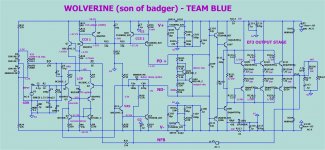
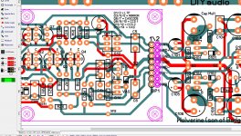
OK , FINAL (below) D8 zener/ or R5 option. Q5 GONE.
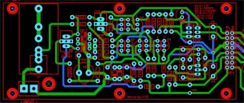
PCB reflects these changes.
I'm going to do one more check to see if the devices/holes conform to
UMS specs and submit it.
OS
OS
The EF3 is proven.
The Wolverine is the simple default amp. I would build it (if it was the only option). If it was not simple , some would not.
Look at the majority of forum designs , the simple ones get built.
Look at Pass , single semi's.
But , to please even a more diverse group .... the open ended nature
of the interface will fill that need. (I want "spooky")
.OK , FINAL (below) D8 zener/ or R5 option. Q5 GONE.
PCB reflects these changes.
I'm going to do one more check to see if the devices/holes conform to
UMS specs and submit it.
OS
OS
Attachments
All good OS,The EF3 is proven.
The Wolverine is the simple default amp. I would build it (if it was the only option). If it was not simple , some would not.
Look at the majority of forum designs , the simple ones get built.
Look at Pass , single semi's.
But , to please even a more diverse group .... the open ended nature
of the interface will fill that need. (I want "spooky")
OK , FINAL (below) D8 zener/ or R5 option. Q5 GONE.
PCB reflects these changes.
I'm going to do one more check to see if the devices/holes conform to
UMS specs and submit it.
OS
OS
Thanks for putting forward what you think is best after considering all options. Can you post a sprint layout file to so I can help with the final check?
2. - C3/4 and C7. C3/4 can go as low as 10pF with 2.2 - 3.3pF lead compensation.
This amp has crazy bandwidth. Optimal with C3/4 = 15pF
and LC/C7 at 2.2pF (below 2). Margin is better than the Wolverine even
at this obscene UG.
OS
Spooky V2
Try this:
C3/C4 - 12p
Add 180p across VAS resistors R16/R21
15dB GM / 81degress PM
LG @ 20Khz 41dB
What about TMC/TPC ?
Thank you Os,The EF3 is proven.
The Wolverine is the simple default amp. I would build it (if it was the only option). If it was not simple , some would not.
Look at the majority of forum designs , the simple ones get built.
Look at Pass , single semi's.
But , to please even a more diverse group .... the open ended nature
of the interface will fill that need. (I want "spooky")
OK , FINAL (below) D8 zener/ or R5 option. Q5 GONE.
PCB reflects these changes.
I'm going to do one more check to see if the devices/holes conform to
UMS specs and submit it.
OS
OS
so this is the final version of wolverine.
what value for R5 (option)?
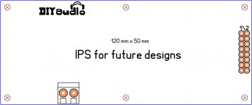
can I say something? please don't kill me xD
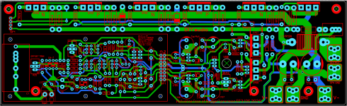
the IPS board holes is a bit off that can be fix is just
micro adjustments I would change the grid to 0.25mm
then I would then make the outline snap to grid after
that is done then I re-adjust the IPS PCB outline to a
solid number is now 120 mm x 50 mm also what is
need it to do is re-adjust all holes of the PCB so they be
exactly 180 degree in Sprint Layout 6 is actually "0" Angle: 0°
one way to do it is be placing a silkscreen circle with a 6.50 mm
diameter close to the edge of the IPS silkscreen then use the
circle as a grid make sure that automatic capture is on,
ok so far after adjust PCB outline to the 0.25 mm grid I
was able to adjusted to 120 mm x 50 mm nice, ok so now
the distance between the holes for the M3 standoff have
a distance of 56.750 mm long side and wide is 43.500 mm
oh yes and you can even go fancy with the rounded corners
too lol I attached the file ST so you guys can see what I mean
edited: is fine the middle hole top
Attachments
Last edited:
can I say something? please don't kill me xD
the IPS board holes is a bit off that can be fix is just
micro adjustments I would change the grid to 0.25mm
then I would then make the outline snap to grid after
that is done then I re-adjust the IPS PCB outline to a
solid number is now 120 mm x 50 mm also what is
need it to do is re-adjust all holes of the PCB so they be
exactly 180 degree in Sprint Layout 6 is actually "0" Angle: 0°
one way to do it is be placing a silkscreen circle with a 6.50 mm
diameter close to the edge of the IPS silkscreen then use the
circle as a grid make sure that automatic capture is on,
ok so far after adjust PCB outline to the 0.25 mm grid I
was able to adjusted to 120 mm x 50 mm nice, ok so now
the distance between the holes for the M3 standoff have
a distance of 56.750 mm long side and wide is 43.500 mm
oh yes and you can even go fancy with the rounded corners
too lol I attached the file ST so you guys can see what I mean
edited: is fine the middle hole top
Vargas , only a 1 row SIP on a 3rd party IPS board.
OS
Hi OS.
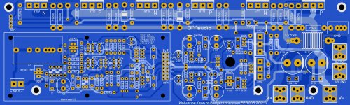
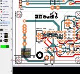
I was Talking to Harry and he suggested moving the input cap C1 away from the output stage. So I had ago at doing that.
What are your thoughts?
# 1 . I took both your idea and Vargas's and integrated them.
C1 is split for us that use normal input caps and is verticle.
Offset has better access , holes with rings are aligned 55mm apart.
This is IPS standard - we have to get this right.
PS - you triggered me , Stuart ... you check it !!
OS
Attachments
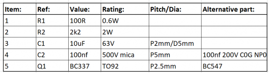
Any suggestions as to what pieces of data should be in an Excel spreadsheet as a BOM?
Not sure but this kind of information is useful to me:
Attachments
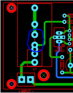
# 1 . I took both your idea and Vargas's and integrated them.
C1 is split for us that use normal input caps and is verticle.
Hi OS,
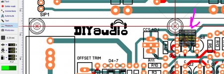
Shouldn't the pads circled in blue have a trace connecting them? Or is this intentional with your "split" comment? Maybe I'm not properly comprehending how it would be used.
Attachments
Hi OS,
Shouldn't the pads circled in blue have a trace connecting them? Or is this intentional with your "split" comment? Maybe I'm not properly comprehending how it would be used.
That will further isolate the input if you use a standard 5-12mm poly cap.
jumper the isolated pad/ trace if you want big ones.
OS
Not sure but this kind of information is useful to me:
I'm compiling a text with the raw data on the optimal components that I
have based my layout on.
NO special unobtanium devices OR values - all standard ... only about 10
values in the whole amp's 52 resistors.
For example , the D8/R5 option .... https://www.mouser.com/datasheet/2/427/tzxserie-1767901.pdf Very low noise.
Or the "Spooky" IPS red led's - https://www.mouser.com/datasheet/2/678/AV02-1562EN_DS_HLMP-x15x_2018-07-23-1827993.pdf
1.6Vf just like my model...
OS
- Home
- Amplifiers
- Solid State
- DIYA store "Wolverine" (Son of Badger) .... suggestions ??