Jeff I do not think they are concerned about efficiency. It takes time to learn a new tool. If you have used pcb design software once you have a leg up but there is always getting use to anything different or taking a mind set shift on a different way to get the same result in the end.
I export to STEP and import into CAD, Im using Autodesk inventor, but Fushion 360 is about the same.
Ive attached a STEP exported from KiCad so you can import into Fusion to see for yourself.
Regards
That's a very handy option! .step file work. I'm surprised Eagle doesn't do this being it's part of the Autodesk group. There's some flaky option to import a board file from eagle into Fusion, but it doesn't work very well.
I've spent time using both eagle and kicad. In my opinion Kicad is much easier to use and when they release Kicad 6 its all over for eagle. Why would you pay for eagle when kicad is free.That's a very handy option! .step file work. I'm surprised Eagle doesn't do this being it's part of the Autodesk group. There's some flaky option to import a board file from eagle into Fusion, but it doesn't work very well.
This is a good introductory project.
Kicad Beginner Tutorial- A Traffic Light for Arduino ( RE-UPLOADED, Twice ) - YouTube
Subscribe to this guys channel he has all the videos to get you started.
Contextual Electronics - YouTube
I just through some transistors on a heatsink so you can see how nice it looks. I got the inspiration to use Kicad from the last model.


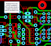
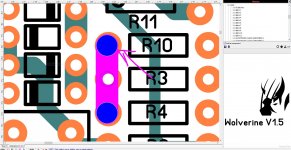
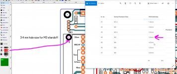
(Below) perfect fit now. Row 2 !! of DIP1 is where it goes. Macro'ed "standard"
holes line up perfect.
Kicad - says won't work on my W7. BS , I have corp. extended support
patches on my 7. Digital signing,AES is just like 8/10.
I go on my son's W10 PC , 7 is all buried in it. M$ just took 7 and "adafied"
it .... no innovation - just a sellout. (below 2}
Kicad is like Eagle + , big modern library ... lots of chips.
Guess I'll learn it.
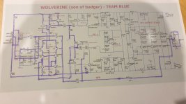
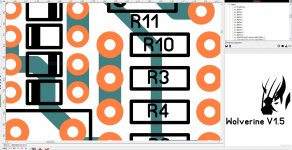
Perfect Wolverine attached , as well.
OS
Just a few tweaks OS
Attachments
Last edited:
...and maybe it will be a store option.
OS
Looking forward to this one!
I'll try an keep my eye on it, no worries.Thank you , Stuart.
Maybe you will help on the "Spook" (below).
A little easier , being symmetric.
I'll show Jason "the spook" , and maybe it will be a store option.
OS
I'll probably take a closer look at the wolverine on the weekend as I'm just so busy during the week.
Question...
Who is creating a BOM for this?
It would be nice to have a bom with optimal components.
I guess resistors and transistors are fairly straightforward but the choice of capacitors is huge.
Hi OS,
I have found some time and started giving the board a close check.
I must say that you have done a great job to keep it so compact.
Amazing really impressed.

Keeping track of all the different small signal transistor pinout's takes a lot of concentration.
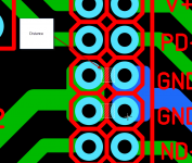
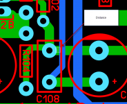
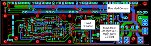
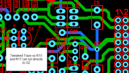
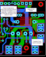
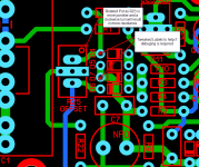
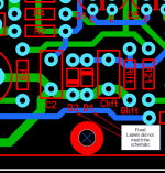
I have found a few small things which I have listed in the image notes.
I will keep going tomorrow night.
I have found some time and started giving the board a close check.
I must say that you have done a great job to keep it so compact.
Amazing really impressed.
Keeping track of all the different small signal transistor pinout's takes a lot of concentration.
I have found a few small things which I have listed in the image notes.
I will keep going tomorrow night.
Attachments
Last edited:
Hi OS,
I have found some time and started giving the board a close check.
I must say that you have done a great job to keep it so compact.
Amazing really impressed.
Keeping track of all the different small signal transistor pinout's takes a lot of concentration.
I have found a few small things which I have listed in the image notes.
I will keep going tomorrow night.
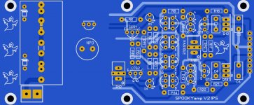
All this present stuff actually has it's roots in Jkuetemann's original layout of
my present "spooky amp".
JK's layout style was DEFINITE inspiration. When I saw that one ,
I stared in wonder !!!
On this one , I ditched the Servo but added the full Zener pass regs. and
the DC blocking cap.
Just as freakin' hair - pulling HARD !! (below).
Wolverine was easier. But , a good intro.
")
Almost have it.
PS - I like all your tweaks .... The store is getting quite a "bang for the buck" - but no buck for me.
My love of the hobby and bringing "class AB" up to a modern standard is enough incentive to ace this.
OS
Attachments
Last edited:
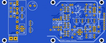
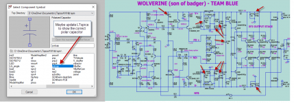
This Spooky has the careful design considerations after reading Thimios's
detailed dissemination of the minor flaws.
Core "Spooky goodness" with LED based Hawksford cascode/LTP CCS's
are preserved. Simulation shows that good balance (H2/3) that decays quickly.
Pass regs. improve PSRR 20db. No hot Zener/resistors ... 15mA (per rail) coolness.
No servo is not a downfall. This exceeds the original simulations in EVERY way.
Builders will have to watch what Vf the CCS leds have - 1.7V is target , a
2.0V LED can be used with R6=430R and a 1K trimmer for R12.
Hawksford cascode LED's don't matter ,just lose a volt at clipping.
OS
Last edited:
- Home
- Amplifiers
- Solid State
- DIYA store "Wolverine" (Son of Badger) .... suggestions ??