0R22 it is. ") Can I do anything more about thermal tracking than the usual practice, i.e, transistors down to the heat sink, emitter resistors elevated from the PCB? In my nearly completed upcoming version (with two NJW0281/NJW0302 output pairs at +/-50V rails) Q10-11-12 are also mounted on the heat sink below the PCB, and not on a separate metal plate above the PCB. Could this be an issue?
Can I do anything more about thermal tracking than the usual practice, i.e, transistors down to the heat sink, emitter resistors elevated from the PCB? In my nearly completed upcoming version (with two NJW0281/NJW0302 output pairs at +/-50V rails) Q10-11-12 are also mounted on the heat sink below the PCB, and not on a separate metal plate above the PCB. Could this be an issue?
Can I do anything more about thermal tracking than the usual practice, i.e, transistors down to the heat sink, emitter resistors elevated from the PCB? In my nearly completed upcoming version (with two NJW0281/NJW0302 output pairs at +/-50V rails) Q10-11-12 are also mounted on the heat sink below the PCB, and not on a separate metal plate above the PCB. Could this be an issue?According to the schematics in #2 and full of hope that this is the ultimate version, it's Q13, a TO-126 device that is installed at the heatsink.Thank you, Kay, I will keep them. I am only uncertain which parts are you referring to under "thermally coupled bias spreader"?
Best regards!
That should not matter. Q10-11-12 are outside of the thermal feedback loop (which is between the Vbe multiplier, driver, and output transistors).Q10-11-12 are also mounted on the heat sink below the PCB, and not on a separate metal plate above the PCB. Could this be an issue?
Ed
Thank you, Ed, for confirming. This was my intuition but I feel safer this way.
Some further changes which I implemented after experimenting with my original version:
I hope to finish the assembly, measure and listen in the next few weeks. If it does not catch fire but pleases my ears, I will share the alternative design, of course.
Some further changes which I implemented after experimenting with my original version:
- Different PCB layout for less cross-talk between the high-current and small-signal parts and for more left-right symmetry
- On-board PSU (30mF/rail) with active rectifier bridges
- On-board solid-state speaker relay
- Two output pairs at +/-50V for 8R speakers (should be also safe for 4R speakers)
- OS and small-signal rail separation by capacitance multiplier (somewhat similar to Wolverine) rather than RC filtering
- As just mentioned, Q10-11-12 are also mounted on the heat sink below the PCB, no need for additional metal plates
- KSC3503 / KSA1381 instead of MJE340 / MJE350 (this mod very audiably improved the mids and highs)
- For the small-signal BJT pairs I used Toshiba HN1C01F-GR and HN1A01F-GR smds (SOT-753) for best hFE matching and thermal coupling. Consequently, I left out the R17 pot for offset adjustment (if the latter was a naive mistake I can still - more painfully - account for it by playing with the R15-16 values)
- In my setup C2, C3, C18, C19 did not make a difference (scope & ears), so I left them out (not so elegant but easy to re-install them piggiback, if still needed)
- According to some literature research, the output coil + resistor were not necessary in my setup (conventionally built, easygoing speakers), so I left them out
- Concerning the grounding scheme I followed Self Fig.25.1: Instead of input GND lifting (D1-D2-R4) + star GND - loop breaker - chassis, I routed the input GND to the chassis right away and did not do the GND lifting
I hope to finish the assembly, measure and listen in the next few weeks. If it does not catch fire but pleases my ears, I will share the alternative design, of course.
I got thru the check stage for starting up the right channel:
LEDs working
R17 1-2mV
R7 < 0.5V
R30 12-20mV
All using the DBT
replace 10R resistors with fuses and started to bias. DBT went on than off as desired.
R17 remained in the 1-3 mV range
R30 was hard to achieve a stable setting. I would get it to ~ 20mV, but then it would start to swing
R7 was a problem. I could not use it in the mV range. Only DCV range and there is hovered around 4 to 5 DCV depending on the R30 setting. Obviously way too high.
The only output transistor that got warm was Q20.
Clearly I have problems and will go over the board again.
If the above description suggests any likely areas to focus on, I appreciate any direction.
Oh, and happy holidays. I had some quiet time so thought I'd put it to good use. So far though, only coal in my stocking.
If you're measuring across R14 to set R7, you should be at 8.25 Volts, not mV. You don't have enough current flowing through the input stage. This will likely affect the output stage bias current (R30) so turn it down before setting the input stage current.
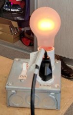
Output stage current will act strange with the light bulb hooked up. You can usually make the bulb start to glow by turning up the bias.
Output stage current will act strange with the light bulb hooked up. You can usually make the bulb start to glow by turning up the bias.
R14 is steady at 8.20~DCV
R30 swings. I'm targeting 25 - 30 mV but just when i think I have it settled, it either starts to either go low to 1mV or head for 40mV++at which point I turn things down, so I don't know if it would keep climbing to burn out? The output transistors range from 92 to 143+ F.
Thanks for the alert about the DBT glowing as the bias increases.
soft start is not cycling.Is your softstart cycling? It sounds like you power supply is drifting around because of the light bulb. Can you get it to run steadily at 20mV now?
I will try again tomorrow. But not hopeful.
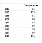
Q13 is mounted to heatsink with the outputs. Its temp was consistent at 89 - 93 over the 30 minutes I took temps readings for each output.
At some point should I try without the DBT in place?
Just checked the R30 pot setting, Currently at 313.6.ohms
R7 is at 55.9 ohms
Last edited:
Here is an approved latest schematic (version 2.5.4) from Stuart. It’s what I would use to generate a BOM or to update the BOMs listed on the diyaudiostore webpage for the Honey Badger. The schematic is annotated as such it details the measurements needed for input stage bias, output stage bias and dc offset. In addition the two options for the cascode voltage reference of the LTP input pair are detailed. You can choose between Zener or Luxman.Sorry to sound like a broken record but is there an approved/sanctified schematic and current BOM of stuff that is widely available?
Best,
Anand.
Attachments
Finally got back to business.Is your softstart cycling? It sounds like you power supply is drifting around because of the light bulb. Can you get it to run steadily at 20mV now?
I was running the right channel and achieved after 10+ minutes:
R14 8.19 DCV
R30 20.mV [it was still fluctuating, but not as widely as my previous attempt to bias]
R17 3.4 mV
The amp was on for about 15 minutes and the bulb started to burn bright as I was adjusting the bias.
Then here was a click and the soft start started cycling, so I shut everything down.
Below are the temperatures of the transistors just before I shut it down.
Is this progress?
Attachments
Well, things didn't go as planned.
I removed the DBT and started increasing bias up to ~18.0 mV when the bias started moving up without adjustment and even though I was dialing down the bias, I couldn't stop it. I heard a click and the two LED lights went out.
I have examined the board for damage, but a visual exam doesn't reveal anything amiss.
I turned things on today and no power is flowing to the amp board. Led lights are off.
The PSU is working as normal at 63.0 DCV +/-.
- Home
- Amplifiers
- Solid State
- diyAB Amp The "Honey Badger" build thread