thank you both for taking the time to explain this to me. I did find that f4 build guide with 6l6 insight on the grounding, good stuff. I'm confident I have a proper grounding now.
https://www.diyaudio.com/community/threads/a-guide-to-building-the-pass-f4-amplifier.234355/
so now, understanding both primaries will need to have inrush protection by the CL60, what i could do is use one CL60 bridged between the IEC hot and both of the red primaries. This would satisfy inrush protection for RED(1, 2) and BLACK(1, 2) primaries, correct?
That would restrict both primaries more than using two CL-60s. A single CL-60 is rated for 5 amps and your F4 amp should use around 1 1/2 amps so there shouldn't be an issue with it being overloaded. I would order another CL60 if you don't already have it and install it. You can use the amp in the meantime with just one.
Another option it to use a 3-watt 10 ohm resistor from your power supply ground to the chassis ground instead of a CL-60. Maybe that will free one up so you can use it on the primaries in the off chance that you already have the part.
Measure the voltage after the CL60 from the mains power and check the temperature of it. So long as things aren't getting too hot or the voltage isn't dropping, you should be fine.
So long story short, Running the mains hot through a single CL-60 and then to the red leads of both your primaries won't kill the amp and will make for an interesting experiment.
I am actually building an Aleph J, that information was lost in the forms a few posts back haha. The aleph J works at 1.7 amps per channel so i should still be ok.
I do have a few CL60's in the mail that i should be getting later this week. I just so happen to have a couple 10ohm resistors that i can use for the power supply ground.
There is a recently built dim bulb tester sitting on my desk and im just dying to see those PS LED's light up, i will give er a go and report back.
Very nice. Those voltages are with no load. Still, progress. They will drop when you have a load on them. The DC voltage will come down a bit after you install the amps and start to bias them up. The mains might also with the one CL-60.
Also, it is best to put the transformer towards the front of the chassis. Your signal wires etc are in the back so you want to keep all of that stuff away from the transformer.
The Aleph J is a fantastic design. It lacks defined bass but you won't miss it with what it does for the mids and highs. It will be hard to turn that amp off.
Last edited:
Cant wait to get the amp boards up and running! currently delayed, waiting on my cable shipment. I will continue to monitor the solo CL60 situation, i do have more on the way so, easy fix if it shows problematic. If not, less is more in my book. I think i will be keeping that 10ohm resistor on the ground. Definitely not just because i like looking at Vishay resistors, haha.
Thats a good point, transformer separation from the signal wires. This layout was influenced by another builder who valued shortest path possible, i think there's value in that. Anyways, i do need to find solution for better separation between transformer and signal wires. This is a 5u chassis, it filled up pretty quickly on that center axis. The IEC i chose may have taken up more real-estate than its worth.
Twisting wires is on the list.")
Thats a good point, transformer separation from the signal wires. This layout was influenced by another builder who valued shortest path possible, i think there's value in that. Anyways, i do need to find solution for better separation between transformer and signal wires. This is a 5u chassis, it filled up pretty quickly on that center axis. The IEC i chose may have taken up more real-estate than its worth.
Twisting wires is on the list.
Attachments
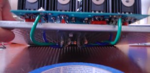
The 10ohm resistor to ground cannot flow all the fault current if there is a big issue, where a CL-60 can. Please replace it as soon as you are done testing. Our use a big diode bridge wired as a groundbreaker.
Please do not put wires through holes in metal without a rubber grommet protecting the wire.
The single CL-60 on the primary might work, but you’ll have to monitor the temp under load. It’s going to get VERY hot, check datasheet for acceptable operating temps. The current mounting scheme and connections to the primary are not acceptable for anything other than testing the PSU, and even then having that much exposed bare conductor is simply dangerous.
The filtered IEC is nice, and worth the bother.
Yes, generally speaking it’s going to be quieter if you have the transformer at the front of the chassis.
If you run out of room, you can mount the transformer and filter board asymmetrically… it will work just fine. Also vertical mounting the transformer frees up a lot of room, that is also a good option.
https://cdn.shopify.com/s/files/1/1006/5046/files/P-PSU-1V30-schematic.pdf
Works for me…
Edit: didn‘t see all those posts inbetween, sorry.
Works for me…
Edit: didn‘t see all those posts inbetween, sorry.
Last edited:
Thank you very much! Is there a corresponding BOM? Sorry for asking, but that link doesn’t work either…https://cdn.shopify.com/s/files/1/1006/5046/files/P-PSU-1V30-schematic.pdf
Works for me…
Edit: didn‘t see all those posts inbetween, sorry.
Thank you for the advice and pointing out those safety concerns. I will address them before i hook up the amp boards.The 10ohm resistor to ground cannot flow all the fault current if there is a big issue, where a CL-60 can. Please replace it as soon as you are done testing. Our use a big diode bridge wired as a groundbreaker.
Please do not put wires through holes in metal without a rubber grommet protecting the wire.
The single CL-60 on the primary might work, but you’ll have to monitor the temp under load. It’s going to get VERY hot, check datasheet for acceptable operating temps. The current mounting scheme and connections to the primary are not acceptable for anything other than testing the PSU, and even then having that much exposed bare conductor is simply dangerous.
The filtered IEC is nice, and worth the bother.
Yes, generally speaking it’s going to be quieter if you have the transformer at the front of the chassis.
If you run out of room, you can mount the transformer and filter board asymmetrically… it will work just fine. Also vertical mounting the transformer frees up a lot of room, that is also a good option.
Try here: https://diyaudiostore.com/collections/frontpage/products/universal-psuThank you very much! Is there a corresponding BOM? Sorry for asking, but that link doesn’t work either…
Scroll down the page, just above the customer reviews.
Hello Besties! In preparation for this post I read the last 20 pages of this thread. But I'd like to run my ideas by you experts before placing any orders.
I will be building F5T 100w-ish monoblocks. My secondaries are 30VAC. I'll be using one PSU board per mono stuffed as follows; 22KuF/63V caps (considered overkill by most, but the UCC 22kuf's were the most economical board-fitting cap at Mouser), four 0.47R 1/3W resistors per rail (should these be upped to 5w given my voltage?), 10k/3w bleeders, and the MUR3020w left over from my transistor kits, as I will be omitting them in the output boards. I'm thinking I'll just omit the snubbers and the LEDs, unless any of you recommend otherwise. Are these sound choices given my operating parameters?
Off-topic; is anyone making original-style Aleph chassis/heatsinks these days?
22,000uF 63V will be great.
You need more 0.47 3W resistors, 6 or 7 per side. This is why the "r optional" exist on the PSU board.
Bleeder is good.
Yes, use the MUR3020 for the PSU, awesome choice. Overall PSU sounds spot on for the job, and will be able to be used in higher voltage projects if you ever want to.
Heatsinks - no, sadly.
You likely meant 3W resistors, but just in case... see the schematic for the F5T ... some additional "optional" resistors may be included on your board. Those 3W parts are fine, but I'd err on the side of caution and install them per the schematic.... four 0.47R 1/3W resistors per rail (should these be upped to 5w given my voltage?),
10k/3w bleeders,
Sure
Wise choice, IMO, to remove them from the output boards.and the MUR3020w left over from my transistor kits, as I will be omitting them in the output boards.
I've never seen anyone say they could hear a difference using the input or output snubbers, but maybe someone has. My general gist has been that since most of the values for common transformers are available in the 'Quasimodo' thread... I just go ahead and install the input side.I'm thinking I'll just omit the snubbers and the LEDs, unless any of you recommend otherwise. Are these sound choices given my operating parameters?
Edited to add - Jim's always fastest.
Thanks Guys!
Yes, I meant 3w. I haven't been drinking. Promise! Is the addition of the optional .47R resistors for the added power rating? Lower resistance? Both?
Too bad about the heatsink/chassis. It was such an iconic look!
Yes, I meant 3w. I haven't been drinking. Promise! Is the addition of the optional .47R resistors for the added power rating? Lower resistance? Both?
By this, do you mean install all 7 per rail? or up them to 5w?Those 3W parts are fine, but I'd err on the side of caution and install them per the schematic.
Too bad about the heatsink/chassis. It was such an iconic look!
- Home
- Amplifiers
- Power Supplies
- diyAudio Power Supply Circuit Board v3 illustrated build guide