More progress - Voice Coils
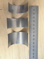
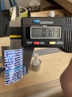
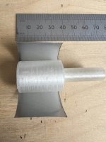
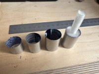
I have printed out the voice coil former mandrel for Option One and wound some thin Aluminium coil formers. The Aluminium comes from a beverage can and is very thin, 0.10mm in thickness. In case this is too thin I can wind two or more layers on the mandrel with epoxy as the adhesive to form a laminate.
I am also trialing two length of voice coil and will see just how minimal a voice coil former I can get away with.
Next step is coil winding.
Burnt
Attachments

- Choose a suitable exciter: Select an exciter that matches the size and resonance frequency of the panel or membrane. Exciters are typically small, lightweight devices that attach to the back of the panel with an adhesive.
- Determine the desired frequency response: Determine the frequency response that you want to achieve from the DML panel. This will depend on the size of the panel, the resonant frequencies, and the intended use of the speaker.
- Design the panel: Design the panel or membrane to optimize the desired frequency response. The panel should be lightweight, rigid, and able to support the weight of the exciter.
- Determine the placement of the exciter: The exciter should be placed at a point on the panel where the resonant modes are most effective at generating sound. This will typically be at a node or antinode of the panel.
- Test and adjust: Once the exciter is attached to the panel, test the DML speaker and adjust the placement of the exciter or the design of the panel as necessary to achieve the desired frequency response and sound quality.
Hello BurntEddy Currents
I am surprised how strong the Eddy currents are in such a thin sheet of Aluminium
Nice to see you again
Seeing the post with the aluminum coil former, I was a bit surprised because I didn't expect seeing metallic coil former then I just remembered that it is used in loudspeaker for the thermal performance. What is around the Eddy current is not clear in my mind. I remember also that in some motor designs there is a ring of copper I think to limit the inductance not sure.
Could you refresh my knowledge?
Is a conductive voice coil former suitable for a full range motor?
Your voice coil former being made from a rectangular metal portion, how is done the mechanical and maybe electrical continuity at the edges?
Christian
Last edited:
Hi Christian, thank you, I am getting there.
Great questions. Yes you are right that I have chosen aluminium for cooling purposes and therefore power handling. I also intend to experiment with ferro fluid in the gap to achieve the same goal. However I have been surprised by the strength of the eddy currents experience particularly as at this stage the voice coil gap is large and the mass of the Aluminium is very low. On the positive side it may imply the the field strength in the gap is high. It is impossible to measure directly with my magnetometer.
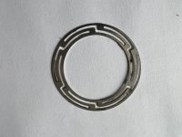
Eddy currents occur in the voice coil, in any ferromagnetic materiel in the pole close to the voice coil, and in a metal former. Soft iron in the poles, which is ideal from a magnetic field perspective, also exhibits high levels of eddy current. All eddy currents are forms of distortion and so all speakers exhibit that distortions to a greater or lesser extent. To offset this I am not using any iron in the pole pieces for Option 1, I am using the neodymium magnets directly. I will be using a shorting ring to reduce eddy current further. This paper is long but its a useful guide to eddy currents and their many effects in a loudspeaker motor. http://diy-audio.narod.ru/litr/FaradayRingsVoiceCoilImpedance.pdf
The Aluminium voice coil former may also function as a shorting coil but there is a difficulty. All voice coil formers have a slit in them to allow for thermal expansion. I am following this principle for now but it obviously precludes the Aluminium former from closing as a coil. I hope to allow for this by winding a shorting coil onto the former but using a turn or two of uninsulated copper wire or aluminium wire to close the coil. This is very much an experiment and I can always revert to Kapton or similar materials for the voice coil former if it fails.
Yes the shorting ring affects inductance and impedance
The use of a aluminium former is usually associated with high power bass speakers because of the need to control cooling and therefore increase the power handling. However, some tweeters of old, Celestion for example, used aluminium domes and extended the skirt of the dome to act as the voice coil former so I am not anticipating a problem with high frequencies. I think its worth trying as a full-range motor. If it fails I can always revert to a more conventional approach.
I am sorry but a dull head means I do not understand the following
"Your voice coil former being made from a rectangular metal portion, how is done the mechanical and maybe electrical continuity at the edges?"
So if you could expand a bit I will try to answer.
Thank you for your questions Christian, they are always helpful
Burnt
Great questions. Yes you are right that I have chosen aluminium for cooling purposes and therefore power handling. I also intend to experiment with ferro fluid in the gap to achieve the same goal. However I have been surprised by the strength of the eddy currents experience particularly as at this stage the voice coil gap is large and the mass of the Aluminium is very low. On the positive side it may imply the the field strength in the gap is high. It is impossible to measure directly with my magnetometer.
Eddy currents occur in the voice coil, in any ferromagnetic materiel in the pole close to the voice coil, and in a metal former. Soft iron in the poles, which is ideal from a magnetic field perspective, also exhibits high levels of eddy current. All eddy currents are forms of distortion and so all speakers exhibit that distortions to a greater or lesser extent. To offset this I am not using any iron in the pole pieces for Option 1, I am using the neodymium magnets directly. I will be using a shorting ring to reduce eddy current further. This paper is long but its a useful guide to eddy currents and their many effects in a loudspeaker motor. http://diy-audio.narod.ru/litr/FaradayRingsVoiceCoilImpedance.pdf
The Aluminium voice coil former may also function as a shorting coil but there is a difficulty. All voice coil formers have a slit in them to allow for thermal expansion. I am following this principle for now but it obviously precludes the Aluminium former from closing as a coil. I hope to allow for this by winding a shorting coil onto the former but using a turn or two of uninsulated copper wire or aluminium wire to close the coil. This is very much an experiment and I can always revert to Kapton or similar materials for the voice coil former if it fails.
Yes the shorting ring affects inductance and impedance
The use of a aluminium former is usually associated with high power bass speakers because of the need to control cooling and therefore increase the power handling. However, some tweeters of old, Celestion for example, used aluminium domes and extended the skirt of the dome to act as the voice coil former so I am not anticipating a problem with high frequencies. I think its worth trying as a full-range motor. If it fails I can always revert to a more conventional approach.
I am sorry but a dull head means I do not understand the following
"Your voice coil former being made from a rectangular metal portion, how is done the mechanical and maybe electrical continuity at the edges?"
So if you could expand a bit I will try to answer.
Thank you for your questions Christian, they are always helpful
Burnt
Hello Burnt,"Your voice coil former being made from a rectangular metal portion, how is done the mechanical and maybe electrical continuity at the edges?"
Excellent, I learnt a new word "dull"... I don't think it applies! Just words (coming from a French guy) without drawing might be a bit difficult. In fact I think you have answered.
The voice coil is made from a rectangular piece of aluminum. To form it as a cylinder you roll it around some cylindrical tool. the long edges of the rectangle becomes then circles, the 2 short edges come close to each other. My question was how to you make the assembly of those two edges... in fact I understand you keep a short space (slit in your post) to manage the effect of temperature.
Clear!
Really impressive what you are doing.
Christian
Notes on a Commercial Exciter
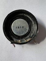
As a brief side note I took apart a damaged Dayton DAEX32EP-4 to see what was inside and to provide a reference of a successful design. It was interesting.
The magnet assembly is based on a single steel magnet 31mm diameter by 7mm deep. This is attached to a pressed steel shell that forms the return path for the field and the outer pole, the magnet itself forming the inner pole. The voice coil gap is 1.62mm.
I have included a photograph of the magnetic field in the voice coil gap using magnet paper.
The magnet design is all steel with is a bit of a surprise and there is no mitigation of eddy current distortion that I can see.
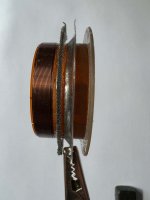
The voice coil has a polymer former, probably Kapton, with a thickness is 0.15mm and a second kraft paper layer for the suspension attachment. The voice coil is single layer 24 turns of 0.25mm dia (AWG 24) copper magnet wire. Given the coil diameter of 32.6mm this means a total L of 2.458 metres. The voice coil measured depth is 6 mm.
The claimed BL performance of this exciter is 4.2Tm (Tesla/metre) which implies a voice coil field of 1.7 Tesla or 17,000 Gauss. This seems a little high for a steel based magnet but I have no way of directly measuring the field in the gap. What it implies is that the depth of the outer pole is kept small to concentrate the field and from visual inspection ( very difficult to achieve) that appears to be the case. I estimate the pole to have a depth of 3mm but I am tempted to section the magnet assembly to check. I will update with another post if I do.
The combination of 6mm depth of the coil and circa 3mm for the magnet pole means the motor is an overhung design to ensure linearity. Unfortunately the trade off will be a reduction is efficiency.
The Dayton DAEX32EP-4 has two suspension methods. The spring steel one that you can see from the outside and a resin impregnated corrugated fabric suspension providing a second suspension. The two suspensions have a very different compliance with the steel suspension being very stiff. This might lead you to assume the stiffer suspension would dominate the suspension performance but its a bit more complex than that.
The steel spring is attached to the voice coil via an aluminium foil ring visible in the photograph. The inner diameter of the spring steel is 42mm and the diameter of the voice coil is 32.6 mm at the point of connection which means that the 0.08mm thick aluminium foil ring is unsupported for 5mm giving it the ability to flex. This forms a third suspension element which will lead to complex suspension behaviour and so we cannot assume the stiff steel spring dominates the suspension behaviour.
In summary the Dayton DAEX32EP-4 is a decent commercial design which I have used with success but there are some obvious points that could be improved where cost is no object.
The suspension system is complex and because of that complexity will introduce non-linearities. The best suspension is no suspension if that can be achieved.
The use of steel for the magnet and the pole-piece will introduce eddy currents and further non-linearities. Interestingly eddy currents increase with frequency reducing high frequency output which is a common trait for exciters. You either need to reduce the eddy currents by use of shorting coils or use a non-ferrous motor design if possible.
An overhung motor is the standard because copper is cheaper than magnetic material even if it is steel. However linearity can also be achieved by making the motor underhung and, as exciters typically have very low displacement this is a feasible option.
The wire thickness is high for a tweeter, which is typically 0.1mm or 38AWG, and low for a woofer which is typically 0.32mm 0r 28AWG. This is the typical full-range compromise. However, it may be possible to use a mix of wire gauges in a two layer custom voice coil as an alternative.
All in all interesting and informative. Images below.
Burnt.
As a brief side note I took apart a damaged Dayton DAEX32EP-4 to see what was inside and to provide a reference of a successful design. It was interesting.
The magnet assembly is based on a single steel magnet 31mm diameter by 7mm deep. This is attached to a pressed steel shell that forms the return path for the field and the outer pole, the magnet itself forming the inner pole. The voice coil gap is 1.62mm.
I have included a photograph of the magnetic field in the voice coil gap using magnet paper.
The magnet design is all steel with is a bit of a surprise and there is no mitigation of eddy current distortion that I can see.
The voice coil has a polymer former, probably Kapton, with a thickness is 0.15mm and a second kraft paper layer for the suspension attachment. The voice coil is single layer 24 turns of 0.25mm dia (AWG 24) copper magnet wire. Given the coil diameter of 32.6mm this means a total L of 2.458 metres. The voice coil measured depth is 6 mm.
The claimed BL performance of this exciter is 4.2Tm (Tesla/metre) which implies a voice coil field of 1.7 Tesla or 17,000 Gauss. This seems a little high for a steel based magnet but I have no way of directly measuring the field in the gap. What it implies is that the depth of the outer pole is kept small to concentrate the field and from visual inspection ( very difficult to achieve) that appears to be the case. I estimate the pole to have a depth of 3mm but I am tempted to section the magnet assembly to check. I will update with another post if I do.
The combination of 6mm depth of the coil and circa 3mm for the magnet pole means the motor is an overhung design to ensure linearity. Unfortunately the trade off will be a reduction is efficiency.
The Dayton DAEX32EP-4 has two suspension methods. The spring steel one that you can see from the outside and a resin impregnated corrugated fabric suspension providing a second suspension. The two suspensions have a very different compliance with the steel suspension being very stiff. This might lead you to assume the stiffer suspension would dominate the suspension performance but its a bit more complex than that.
The steel spring is attached to the voice coil via an aluminium foil ring visible in the photograph. The inner diameter of the spring steel is 42mm and the diameter of the voice coil is 32.6 mm at the point of connection which means that the 0.08mm thick aluminium foil ring is unsupported for 5mm giving it the ability to flex. This forms a third suspension element which will lead to complex suspension behaviour and so we cannot assume the stiff steel spring dominates the suspension behaviour.
In summary the Dayton DAEX32EP-4 is a decent commercial design which I have used with success but there are some obvious points that could be improved where cost is no object.
The suspension system is complex and because of that complexity will introduce non-linearities. The best suspension is no suspension if that can be achieved.
The use of steel for the magnet and the pole-piece will introduce eddy currents and further non-linearities. Interestingly eddy currents increase with frequency reducing high frequency output which is a common trait for exciters. You either need to reduce the eddy currents by use of shorting coils or use a non-ferrous motor design if possible.
An overhung motor is the standard because copper is cheaper than magnetic material even if it is steel. However linearity can also be achieved by making the motor underhung and, as exciters typically have very low displacement this is a feasible option.
The wire thickness is high for a tweeter, which is typically 0.1mm or 38AWG, and low for a woofer which is typically 0.32mm 0r 28AWG. This is the typical full-range compromise. However, it may be possible to use a mix of wire gauges in a two layer custom voice coil as an alternative.
All in all interesting and informative. Images below.
Burnt.
Attachments


Last edited:
Hello BurntThe claimed BL performance of this exciter is 4.2Tm (Tesla/metre) which implies a voice coil field of 1.7 Tesla or 17,000 Gauss. This seems a little high for a steel based magnet but I have no way of directly measuring the field in the gap.
Would it help in such analysis to get the BL by the Thiele and Small parameters extractions? It is not too difficult to do it on an exciter thanks to an added mass. See some posts on the main thread
I was looking for a view of an underhung motor to understand how the suspension is organized. Not found in few minutes but I found this paper about Faraday rings. It include a calculation and simulation approach.An overhung motor is the standard because copper is cheaper than magnetic material even if it is steel. However linearity can also be achieved by making the motor underhung and, as exciters typically have very low displacement this is a feasible option.
Christian
- Home
- Loudspeakers
- Full Range
- DML Exciter Design