If you mark a text you want to quote you will see a small sign saying "Quote" popping up just below the marked text - if click that pop-up and hit Quote - the author nick will come along the quote - the we will all know who made the quoted statement.addressing the quote
//
Hi, yeah it was me imagining how the phenomenon in jump resonance paper might work out. Could you help with it? you seem to know how it plays out.
Hi, yeah it was me imagining how the phrnomenon in jump resonance paper might work out. Could you help with it? you seem to know how it plays out.
It's simple conservation of energy. When you push the cone you give it a certain amount of kinetic energy (mV^2/2). As the spring compresses that energy is stored in the spring as potential energy. When the cone stops that potential energy is equal to (mV^2/2). When the spring pushes back the cone moves back and the spring gives back that potential energy by accelerating the driver. When the driver is at the same position it was when you pushed it the spring will have given back all the energy and the cone will now have the same energy, (mV^2/2). To move faster you would have to add more energy.
ehem, you are right  I should have written faster than it should, or something. Of course energy should preserve, I was trying to imagine how the jump resonance woukd trigger, slow sweep towards resonant frequency and the resonating starts suddenly on frequency different from Fs, which would relate to suspension stiffening, shifting the resonant frequency up.
I should have written faster than it should, or something. Of course energy should preserve, I was trying to imagine how the jump resonance woukd trigger, slow sweep towards resonant frequency and the resonating starts suddenly on frequency different from Fs, which would relate to suspension stiffening, shifting the resonant frequency up.Something still doesn't smell right with the whole setup.

Drawing a set of curves on a napkin / engineering paper, we get:
Target Displacement = sine wave,
Acceleration = -sine,
Velocity = cosine,
I(drive)= Acc = -sine,
Vemf = Vel = cosine
(V-drive)
Then we add crossover kinks to Vemf, flattening it near the zero midpoint to account for reduced Bl at the displacement peaks.
Then, V(drive) is almost exactly Vemf, but a slight phase difference gives a small net voltage, and that drives the current (which we assume is very small because of the mechanical resonance).
But, considering the kinks in the Vemf from over-drive, peak current gets a dip followed by a lump, distorting the wave and pushing it sideways. It looks like that should help the displacement linger in the saturated Xmax region. The stronger the over-drive, the longer Vemf lingers around 0V, and so the impedance looks like it would actually be close to DCR most of the time except when the wave switches polarity.
(I-drive)
Now the big change is that we're developing a voltage in response to the impedance and current. I'm not sure how the impedance should really be treated. If it's a cosine with doubled frequency (2 valleys close to DCR @ zero velocity), then the voltage gets a big 3rd harmonic dip where the peak should be, making the voltage a bit square (lots of saturation).
Also, the trouble is that I'm not sure if the impedance dips ever disappear, even at low amplitude. The velocity always crosses zero at all amplitudes, so the instantaneous motional impedance must oscillate between nothing and some peak value. Unless maybe we make it some imaginary vector, so as to prevent the frequency doubling, but I've long since run out of space on my napkin.
Frequency skew
Aside from that, I still can't see how increasing the amplitude somehow increases the resonance frequency. I understand the spring rate could be very progressive. But it would be non-linear, so it wouldn't actually oscillate with a high Q because it would rapidly lose energy as frequency side-bands.
I did a sketch with various sines and cosines that's too embarrassing to paste here, but to take it further, it really needs to be done in software.
Hi,
Sorry it's a bit hard to follow your train of thought so I cannot give you effective answer. Hopefully these little pieces of information can help you find your way.
In general, what is on the jump resonance paper seems to be typical behaviour and not something special for loudspeaker drivers. See for example this one https://www.uio.no/studier/emner/matnat/math/MEK4100/h19/beskjeder/forcedoscillations.pdf
But it is important to remember why we'd even think about such things, why care? If such phenomenon is relevant for system audible performance then we should care a bit at least, so let's try to make connection to real world application.
As the paper linked above refers it is a "hysteretic system", which I understand simplified that output depends on previous output which the test procedure in jump resonance paper also demonstrates, and in that sense it's something to be avoided. Let's assume this is indeed a audible thing, and we have a real application of a loudspeaker with current drive amplifier at hand. Now, assuming the phenomenon was unknown to me adjusting a system: I'd hook the amplifier to the speaker and measure acoustic frequency response and see there would be a peak in the response at resonance, which I would have to deal with somehow. It could be dealt with DSP or conjugation network or adding damping inside the enclosure. Very likely I would add at least some damping no matter what, and perhaps use EQ in addition.
Now, if the jump resonance was a phenomenon I was familiar with, I would opt adding great amount of damping material because I know the frequency response peak would happen "arbitrarily" also above the actual Fs I saw from the measurement I took, then it would be logical to use damping inside the enclosure which is not that much frequency dependent as a notch filter or conjugation network would be. As the frequency response is now fine with enough damping in place, then the problem would not exists anymore like it doesn't with electrical damping.
So, even if we did not fully understand why the jump resonance happens, we can still utilize the information with logic by assuming it is real and then mitigating it and it does not seem to be much of a problem. Or, mitigating it with enough damping does no harm even if the phenomenon wasn't real so it would be fine to add assume it is real and act accordingly just in case. Also, by common sense, the enclosure would likely have at least some damping material inside and perhaps the phenomenon was mitigated already as side-effect.
In addition there is now interesting question that what is good balance of "current drive" and "voltage drive" on system resonance? If the coil jump out is an issue for voltage drive, and jump resonance is an issue for current drive, then it is logical that pure voltage or current drive is not optimal for such system and that there is likely some circuit impedance that is fine compromise. Also, cure for both seems to be enough damping inside the box. Further more, thinking home hifi application, it is possible to make a home hifi system where excursion is not an issue at all, when the system always stays on the linear region of suspension (and BL) so it doesn't matter too much which one it is. This would mean amplifier power required was small and all sorts of distortions would be relatively small, which means the microphone issue would be the only problem left of the three discussed in this thread but if system acoustic distortion is so low that a functioning mic cannot hear it above it's own distortion then I would think it's not very audible in first place and all of these issues just vanished.
Sorry it's a bit hard to follow your train of thought so I cannot give you effective answer. Hopefully these little pieces of information can help you find your way.
Voltage has no effect, unless it makes current and in this sense this is unnecessary detail that just confuses. With current drive impedance of circuit is so high that back EMF voltage makes very little current. With ideal current drive impedance would be infinite, zero current from backEMF. Thus, force to cone is basically zero, so no effect to acoustic domain. And this includes the electrical damping at resonance and distortion output above, where the current would not dampen as it's perpendicular due to mass. Basically backEMF has no effect on the system acoustic output with current drive.(I-drive)
Now the big change is that we're developing a voltage in response to the impedance and current. I'm not sure how the impedance should really be treated. If it's a cosine with doubled frequency (2 valleys close to DCR @ zero velocity), then the voltage gets a big 3rd harmonic dip where the peak should be, making the voltage a bit square (lots of saturation).
You can find info about nonlinear spring mass oscillation with search https://www.google.com/search?q=Nonlinear+spring+mass+oscillationFrequency skew
Aside from that, I still can't see how increasing the amplitude somehow increases the resonance frequency. I understand the spring rate could be very progressive. But it would be non-linear, so it wouldn't actually oscillate with a high Q because it would rapidly lose energy as frequency side-bands.
In general, what is on the jump resonance paper seems to be typical behaviour and not something special for loudspeaker drivers. See for example this one https://www.uio.no/studier/emner/matnat/math/MEK4100/h19/beskjeder/forcedoscillations.pdf
But it is important to remember why we'd even think about such things, why care? If such phenomenon is relevant for system audible performance then we should care a bit at least, so let's try to make connection to real world application.
As the paper linked above refers it is a "hysteretic system", which I understand simplified that output depends on previous output which the test procedure in jump resonance paper also demonstrates, and in that sense it's something to be avoided. Let's assume this is indeed a audible thing, and we have a real application of a loudspeaker with current drive amplifier at hand. Now, assuming the phenomenon was unknown to me adjusting a system: I'd hook the amplifier to the speaker and measure acoustic frequency response and see there would be a peak in the response at resonance, which I would have to deal with somehow. It could be dealt with DSP or conjugation network or adding damping inside the enclosure. Very likely I would add at least some damping no matter what, and perhaps use EQ in addition.
Now, if the jump resonance was a phenomenon I was familiar with, I would opt adding great amount of damping material because I know the frequency response peak would happen "arbitrarily" also above the actual Fs I saw from the measurement I took, then it would be logical to use damping inside the enclosure which is not that much frequency dependent as a notch filter or conjugation network would be. As the frequency response is now fine with enough damping in place, then the problem would not exists anymore like it doesn't with electrical damping.
So, even if we did not fully understand why the jump resonance happens, we can still utilize the information with logic by assuming it is real and then mitigating it and it does not seem to be much of a problem. Or, mitigating it with enough damping does no harm even if the phenomenon wasn't real so it would be fine to add assume it is real and act accordingly just in case. Also, by common sense, the enclosure would likely have at least some damping material inside and perhaps the phenomenon was mitigated already as side-effect.
In addition there is now interesting question that what is good balance of "current drive" and "voltage drive" on system resonance? If the coil jump out is an issue for voltage drive, and jump resonance is an issue for current drive, then it is logical that pure voltage or current drive is not optimal for such system and that there is likely some circuit impedance that is fine compromise. Also, cure for both seems to be enough damping inside the box. Further more, thinking home hifi application, it is possible to make a home hifi system where excursion is not an issue at all, when the system always stays on the linear region of suspension (and BL) so it doesn't matter too much which one it is. This would mean amplifier power required was small and all sorts of distortions would be relatively small, which means the microphone issue would be the only problem left of the three discussed in this thread
but if system acoustic distortion is so low that a functioning mic cannot hear it above it's own distortion then I would think it's not very audible in first place and all of these issues just vanished.
Last edited:
Somewhat related stuff, see how Klippel defines Xmax for a driver:
https://www.klippel.de/fileadmin/kl...plication_Notes/AN_05_Displacement_Limits.pdf
For example max deviation for compliance, motor force and inductance are considered among few other metrics and which ever limits the performance first is the Xmax.
For example, limit for Bl(x) drop "for tolerable distortion" is considered 82%. For compliance the drop is 75%. Anyway, what is interesting the test setup amplifier output impedance is not defined in the document, but I suppose we can assume it is low output impedance, voltage drive, amplifier which is used to determine these values and thresholds. What if there was high impedance in series with the driver, would it change limits for tolerable distortion for the various parameters?
Anyway, Erin publishes a table for the numbers on his driver tests and it's interesting to see that for example Bl related distortion dominates this particular driver that I happened to open up, while on some other it might be compliance.

Drawing a quick conclusion, if one is scared of coil jumping out from the gap perhaps use a driver whose performance is not limited by Bl but something else, or if scared about jump resonance then use driver whose performance is not limited by compliance but something else. Even better, if limits are far enough not to be a concern in the first place.
https://www.klippel.de/fileadmin/kl...plication_Notes/AN_05_Displacement_Limits.pdf
For example max deviation for compliance, motor force and inductance are considered among few other metrics and which ever limits the performance first is the Xmax.
For example, limit for Bl(x) drop "for tolerable distortion" is considered 82%. For compliance the drop is 75%. Anyway, what is interesting the test setup amplifier output impedance is not defined in the document, but I suppose we can assume it is low output impedance, voltage drive, amplifier which is used to determine these values and thresholds. What if there was high impedance in series with the driver, would it change limits for tolerable distortion for the various parameters?
Anyway, Erin publishes a table for the numbers on his driver tests and it's interesting to see that for example Bl related distortion dominates this particular driver that I happened to open up, while on some other it might be compliance.
Drawing a quick conclusion, if one is scared of coil jumping out from the gap perhaps use a driver whose performance is not limited by Bl but something else, or if scared about jump resonance then use driver whose performance is not limited by compliance but something else. Even better, if limits are far enough not to be a concern in the first place.
Btw, the Klippel data has more interesting stuff that relates to this thread. See this https://www.erinsaudiocorner.com/driveunits/sbacoustics_sb17cac35-4/
Scroll down to compression test results, the lows do not compress but expand, the coil jump out stuff visible on a graph? Looks like it, but some other drivers I checked did not have it, like this one: https://www.erinsaudiocorner.com/driveunits/dyn_mw182/ but perhaps here as Fs is very low the expansion is outside the graph.

Erin publishes also a graph showing Fs shift with excursion, related to this thread. I wish there was more of this Klippel data available. AudioXpress Voice coil test bench is another good source, unfortunately there is not as much data as there could be.
Anyone in touch with him, any chance to get this kind of a Klippel with some driver with/without series resistor?
Scroll down to compression test results, the lows do not compress but expand, the coil jump out stuff visible on a graph? Looks like it, but some other drivers I checked did not have it, like this one: https://www.erinsaudiocorner.com/driveunits/dyn_mw182/ but perhaps here as Fs is very low the expansion is outside the graph.
Erin publishes also a graph showing Fs shift with excursion, related to this thread. I wish there was more of this Klippel data available. AudioXpress Voice coil test bench is another good source, unfortunately there is not as much data as there could be.
Anyone in touch with him, any chance to get this kind of a Klippel with some driver with/without series resistor?
Last edited:
I think his user name here is @bikinpunkAnyone in touch with him
I also think probably the low frequency "expansion" may be inaccurate as levels are probably very low?
Klippel paper about the stuff: https://www.klippel.de/fileadmin/kl...Diagnosis_and_remedy_of_Nonlinearities_00.pdf
And here is a paper which Klippel paper(s) refer to, and quite extensively shows jump out phenomenon. Also some familiar looking graphs included https://www.researchgate.net/publication/324171655_Nonlinear_Dynamical_Behavior_of_a_Voice_Coil by Norris.
Only skimmed it through, but it looks like the explanation why jump out happens is there, which is due to DC offset as per in Klippel paper. And one reason for DC offset is when time of returning force (suspension) is slower than excitation (voltage). Klippel shows others, basically all non-linearities together along with content of excitation signal make a complex mix, which leads to DC offset which leads to jump out among other things (lower sensitivity and increased IMD for example). Quite complex interplay in the end.
Snippet from the Norris paper:
When the voice coil enters the weaker BL region, in the numerical example shown in Fig 4.1, its motion is dominated by the stiffness, which determines its time of return. If its time of return is too long, before it again enters the region where BL dominates the applied voltage causes the voice coil to move outwards, causing a constant DC offset.
And here is a paper which Klippel paper(s) refer to, and quite extensively shows jump out phenomenon. Also some familiar looking graphs included
https://www.researchgate.net/publication/324171655_Nonlinear_Dynamical_Behavior_of_a_Voice_Coil by Norris.Only skimmed it through, but it looks like the explanation why jump out happens is there, which is due to DC offset as per in Klippel paper. And one reason for DC offset is when time of returning force (suspension) is slower than excitation (voltage). Klippel shows others, basically all non-linearities together along with content of excitation signal make a complex mix, which leads to DC offset which leads to jump out among other things (lower sensitivity and increased IMD for example). Quite complex interplay in the end.
Snippet from the Norris paper:
When the voice coil enters the weaker BL region, in the numerical example shown in Fig 4.1, its motion is dominated by the stiffness, which determines its time of return. If its time of return is too long, before it again enters the region where BL dominates the applied voltage causes the voice coil to move outwards, causing a constant DC offset.
Last edited:
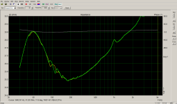
Notice how the boosted area looks like it has a double peak with a small dip in the middle? I'd compare it to the (non-normalised) original, in case it already had a peak there and it ended up being wider. A bigger peak doesn't always have a higher Q. It could be lower.Btw, the Klippel data has more interesting stuff that relates to this thread. See this https://www.erinsaudiocorner.com/driveunits/sbacoustics_sb17cac35-4/
Scroll down to compression test results, the lows do not compress but expand, the coil jump out stuff visible on a graph? Looks like it, but some other drivers I checked did not have it, like this one: https://www.erinsaudiocorner.com/driveunits/dyn_mw182/ but perhaps here as Fs is very low the expansion is outside the graph.
View attachment 1229692
Erin publishes also a graph showing Fs shift with excursion, related to this thread. I wish there was more of this Klippel data available. AudioXpress Voice coil test bench is another good source, unfortunately there is not as much data as there could be.
Anyone in touch with him, any chance to get this kind of a Klippel with some driver with/without series resistor?
Depending on hearing and source material, a peak could be less obtrusive if the Q is reduced. Take, for instance, "walking bass". Without precise bass EQ, there is often a prominent note that is consistently louder than the others, even with sealed woofers that are supposedly overdamped. Widening the peak could spread that energy across several notes. And besides, I'm sure that the actual height of the peak is nowhere near as bad as predicted from Ohm's Law with V sensitivity vs impedance.
BTW I think I'll start doing those battery based click tests that someone suggested recently. It may be possible to fine-tune the practical damping factor and minimise any subjective living room 'boom'. I'm sure I've mentioned this before, but then you're basically balancing 2 independent variables, X and Y, to find a happy medium. Variations in HD and variations in frequency response.
Anyway, I haven't posted those sketches of sine waves, with my limited guesstimates of cone behaviour at the bass resonance. Maybe one day, when I decide to make a home-brew speaker.
Hi,
jeah any non-linear behavior makes sound deviate from the original, which might sound just fine but at least philosophically is something better to avoid in a playback system, at least to some extent.
The peaks on that compression graph could be anything, and perhaps most interesting is just how rest of the bandwidth compresses while the bass doesn't seem to, and could even expand. Trying to imagine how this might sound, it might sound just fine giving "impressive dynamic bass", or just boomy bass accompanied with room modes, and could also lead to driver failure as Hörnli has been promoting. And increased distortion before the failure. Be it good or bad soundwise, well, perhaps not an issue with a home system that is big enough to avoid max excursion situation.
As such it's fun stuff to think about. On the other hand, data like that is hard to obtain without such Klippel measurement system, and thus somewhat out of reach for DIYer other than what data happens to be available from those who have such system. Battery click test sounds good approach, although I'm not sure how you'd differentiate sound of the box from sound of the room? Perhaps conducting the test outside?
ps. check out the Klippel papers. The jump out and distortion problems mainly arise from DC offset of the voice coil, which the enclosure (and damping) doesn't affect at all (was on some of the papers). On the other hand, if I got one driver and need to make it work somehow, then all I can do is optimize the driver / box system and accept the performance. All this stuff on the thread relates mainly how to choose a transducer for bass application, and as you say, building transducers if you are in for that
Last edited:
Forgot to mention, also Hörnli current measurement in post #1 shows this kind of double thingie around resonance, perhaps related, perhaps just coincidence.Notice how the boosted area looks like it has a double peak with a small dip in the middle?
Is this seriously what Audio Precision is using?Hello All,
This is the setup that I use. The resistor is 0.1R.
View attachment 1207770
It is the setup that is internal to the Audio Precision APx1701 transducer test interface. The sense resistor is small compared to the driver impedance on purpose to minimize the resistor's effect on the circuit.
Thanks DT
I was expecting better.
Have the sense resistor inside the feedback loop of the amplifier will give true current readings and isn't hard to do.
Otherwise this will introduce an error.
An error that is small, but it's a error nevertheless that could have been easily prevented for gear with that price tag.
Yes, this is due to the very small reference resistance.Still have to find a solution to deal with the spikes. Any idea?
Leaving not a lot of room for resolution.
I have done a lot of similar measurements in the past, and in this case it's a matter of just averaging a lot.
A much better method is (as I just mentioned above), to go to real voltage amplifier with a reference resistor in its feedback loop.
Rref needs to be of an adequate value, the higher will give a lot more resolution, but also will need an amplifier with very high voltage rails.
The current can be easily calculated as well.
- Home
- Loudspeakers
- Multi-Way
- Drive Current Distortion Measurement