The high Qes value coupled with low efficiency. The damping makes broader but less high resonance. If the resonance frequency is low, not able further compensate the dipole roll off. If you leave the Qts high, "one note bass" is generated around resonance, and a big hole at upper bass region (a lot of full range static make it). At planars can implement a mechanical damping plus electrical dipole roll-off compensation. For example, at the bigger panel's (35Hz) must damp (Qts=2) and add a low pass filter with cca. 50Hz corner frequency. The efficiency will terrible, but the bass can be well controlled. The setup must be variable (Q and corner freq.), controlled by ear.
Wrinex, your measurings are essentials: we couldn't see any measure of planars until now, which works only 1 resonance peak. Most of them are "distributed resonance mode" construction. They are very difficult analisable. But the one peaked construction is informative about possible next steps (electrical and mechanical too).
THen i added damping on one side, but lost the measurement....

Dats is a pain in the *** to work with really dumb GUI.
QTS went down to 4.5. then i added the same mesh on the other side of the magnets. and now dats cant make up the QTS maybe not enough excursion to make up the differences i guess. it shows the response but wont fill in the numbers on the right.

Dats is a pain in the *** to work with really dumb GUI.
QTS went down to 4.5. then i added the same mesh on the other side of the magnets. and now dats cant make up the QTS
maybe not enough excursion to make up the differences i guess. it shows the response but wont fill in the numbers on the right.i really have no clue why they could not include a bit more power in this DATS v3 , all in one thing. would not hurt to add like 2 watts , seem to be just line volume/headphone.
the reason it might have a hard time is because it has 2 main resonances one for each foil. so when the Q gets lower... the bump is rather wide and it cant make up his mind what the FS is for instance. since its much wider as with a normal speaker i believe.
let me tune one foil higher see what it does
Here a distortion measurement of the panel with the dual MESH as seen in the last DATS measurement without any eq.

and second pic is the first panel i measured with DATS with EQ to supress the resonance hump instead of using mesh.
It can be seen the mesh or damping on the inside screws up the distortion. in the mesh panel 3th harmonics shoot up from 100 hz and down. the smaller panel nr 2 without mesh and with eq has far lower distortion down low.
hmm maybe i need to cover the whole magnet structure with mesh. but i am afraid damping might be to big with the mesh i got maybe alter the plate that holds the magnets to create a more gentle damping over its entire surface. by reducing the open area between the magnets.
By using holes for instance and play with thos... like taping some off to see what would be enough damping. i mean it would be cool to implement the required damping in the frame itself. ill try taping a few of the slots see what it does, first remove the mesh again...
maybe alter the plate that holds the magnets to create a more gentle damping over its entire surface. by reducing the open area between the magnets.By using holes for instance and play with thos... like taping some off to see what would be enough damping. i mean it would be cool to implement the required damping in the frame itself. ill try taping a few of the slots see what it does, first remove the mesh again...
SO here are different damping methods distortion
1 No damping

2 Mesh Fine only in the middle

3 Bigger mesh (conductive fabric) entire surface

4 Taped of half the slots between magnets.. this does create scuffing (might be the tapes flapping or to little surface area to move the air between the foils) it also loses on output. so taping of half might be to much, and also to local.

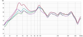
And the frequency response of all 4.
all measured on a stand so the 94hz might be floor relfection ? or walls ? no idea

Pics of the damping


1 No damping
2 Mesh Fine only in the middle
3 Bigger mesh (conductive fabric) entire surface
4 Taped of half the slots between magnets.. this does create scuffing
(might be the tapes flapping or to little surface area to move the air between the foils) it also loses on output. so taping of half might be to much, and also to local.And the frequency response of all 4.
all measured on a stand so the 94hz might be floor relfection ? or walls ? no idea
Pics of the damping
Attachments


Last edited:
that could well be ! i mean xmax is huge, and these magnets can only do so much. still waiting on steel for the push pull. it has the same xmax but twice the magnetic field. but also a much wider space the field is high to put coil in. so fingers crossed ! it should also be easier to damp
Last edited:
The "push-pull" version will be more efficient, but the electric damping will still not be enough alone. However, damping and efficiency can be increased even further with more conductive material at membrane. This seems paradoxon at first glance, but the air mass is the dominant part of moving mass at big planars (100g order of magnitude at your bass panel). A few times 10g weight increment generates little change of mechanical parameters, but the product B*l (at constant resistance) increases in proportion to the square root of the conductor mass. In another wording: the conductive mass and efficiency increase linearly. This is still until the moving force is totally utilisated by air load.
well yes , i mean double coil etc could add a little. or thicker foil in this caseThe "push-pull" version will be more efficient, but the electric damping will still not be enough alone. However, damping and efficiency can be increased even further with more conductive material at membrane. This seems paradoxon at first glance, but the air mass is the dominant part of moving mass at big planars (100g order of magnitude at your bass panel). A few times 10g weight increment generates little change of mechanical parameters, but the product B*l (at constant resistance) increases in proportion to the square root of the conductor mass. In another wording: the conductive mass and efficiency increase linearly. This is still until the moving force is totally utilisated by air load.
and thus more turns- Home
- Loudspeakers
- Planars & Exotics
- Dual membrane planar magnetic (both active driven)