You need to forget all ideas about the plate A being an equipotential circuit node, so it matters exactly where on A you connect things. The secondary CT needs to connect as close as possible to the reservoir caps junction, and as far as possible from anywhere else.
The two output grounds at opposite ends of A will not be at the same potential, so you will have to keep the signal grounds for the two stereo channels separate throughout your entire system; good luck with that!
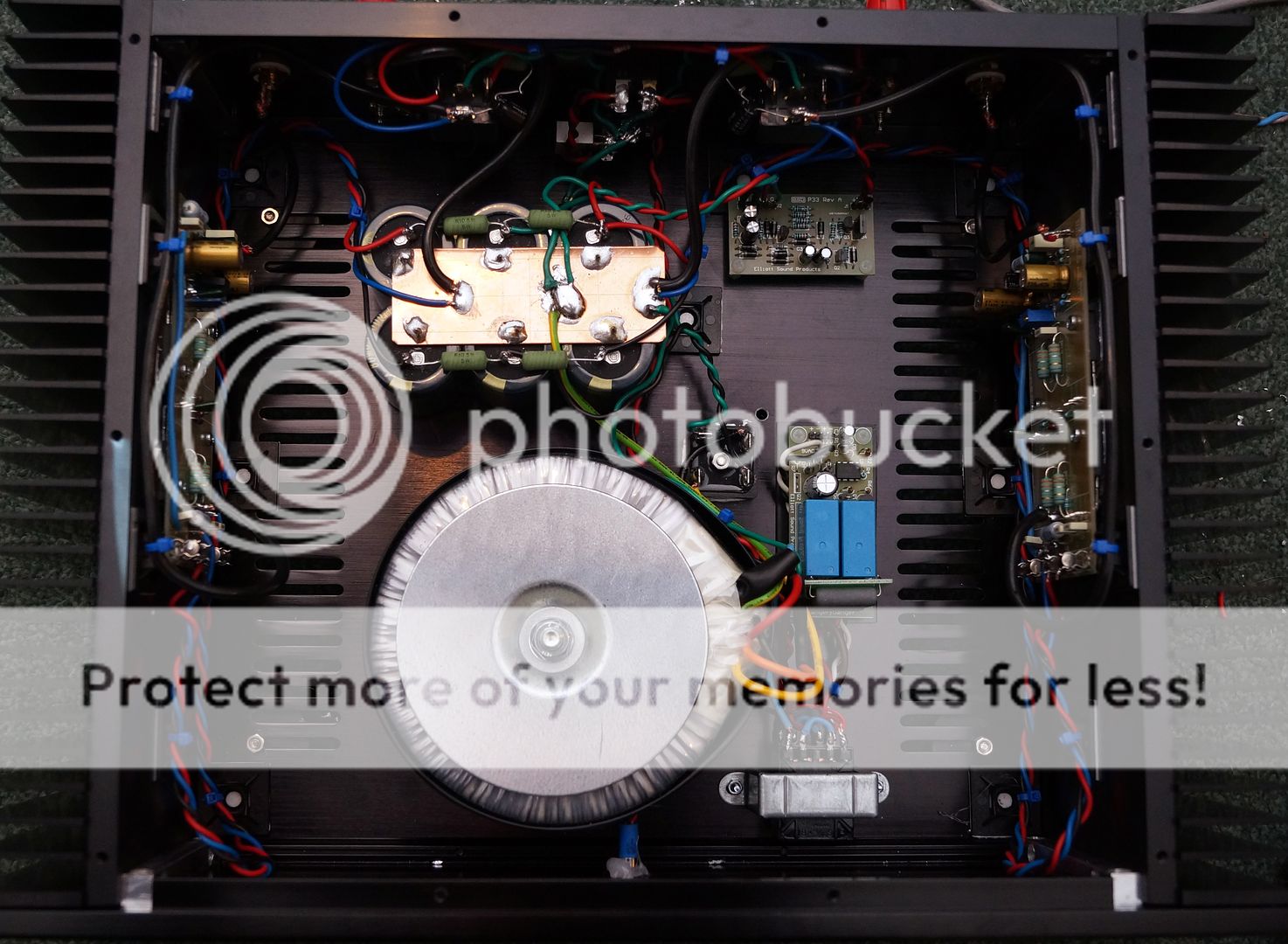
Whoever designed that amplifier did not understand grounding.
The two output grounds at opposite ends of A will not be at the same potential, so you will have to keep the signal grounds for the two stereo channels separate throughout your entire system; good luck with that!
Whoever designed that amplifier did not understand grounding.
No. 40 v AC through a full wave bridge does not = 56.26 V close but you forgot to include the voltage drop across the diodes in the bridge which for a common 35 A bridge will be about 1 v . Ok no big deal but I did want to bring it up as sometimes it does need to be considered. Like once I wanted to run a tube heater at ~ 6.3 V DC and had a 5v transformer so I did the 5 x 1.41 = 7.05 calculation and it looked like that would be just a little high. But I had negleglected the drop across the rectifier . But using a big single diode and 10,000 uf cap I got 6.2v just about perfect.
His PSU has two audio commons, at each end of plate A. Connect both to chassis and you have a loop. Connect just one and the other channel has a signal reference with built-in buzz and crosstalk.
This is another example of 'I want these two things to be connected to each other, and also maintain isolation between them'. You can do monoblocs - completely separate power amps for each channel - or you can do a stereo power amp. You can even do a pair of monoblocs (electrically) in the same (physical) chassis. What you can't do is share one semi-detached PSU between two amps, as the dirty end of the PSU is about the worst possible place to join the channels together - yet this design insists on it!
This is another example of 'I want these two things to be connected to each other, and also maintain isolation between them'. You can do monoblocs - completely separate power amps for each channel - or you can do a stereo power amp. You can even do a pair of monoblocs (electrically) in the same (physical) chassis. What you can't do is share one semi-detached PSU between two amps, as the dirty end of the PSU is about the worst possible place to join the channels together - yet this design insists on it!
Well for all of the negativity and naysaying... it works perfectly. No hum, no noise, no issues.
For clarification;
The signal ground from the inputs is isloated from the chassis at the socket/jack and connects directly to the input of the amplifier board.
The speaker return for each channel connects to the copper plate at the same point as the power ground for each channel. That copper plate is connected to chassis ground at one point only.
Yes, I probably should have connected all of the wires to the copper plate in the same place - I understand that - but I didn't and it still works just fine.
Sounds better than my old amp...
From the design notes:
Note that the P-GND connection goes direct to the star earth point at the filter caps, and that the input GND connection is used only for the input wiring. This seems to cause some confusion. R19 and C13 are used to isolate the input from the main power ground - this is done to eliminate possible earth loops and hum when the amp is connected to an earthed source (preamp, etc).
Congratulations - you've done your own 'diy thing' and learned a lot despite all of the negativity and naysaying of some posts
One suggestion that may do nothing to improve the amp's performance is to maybe shorten the twisted wires from power supply to amp boards - on the other hand, why disturb something that's functioning quite well
If you suffer from a ground loop later on (with perhaps a source component having a ground/chassis connection on the signal wires, source component having a different mains supply point, etc) one way to reduce this is to add a resistance (10 ohm is usual) between your central earth plate and the chassis ground - they call these 'ground breakers', amongst other names)
First Watt and others use something called a thermistor (commonly used one is a CL-10) that works by presenting a normal 'cold' condition of 10 ohms but if any current flows thru it, this resistance drops to 'bugger-all' (a simple alternative to your 'soft start' circuit too)
Don't know if it'll make any difference at all to your amp's performance - just something you might keep in mind for possible problem later on ....
Again, congratulations on 'doing your own thing' (the essence of the diy world) and building your amp
Spare details
esp elliot project 101 Power amplifier spare resistance, capacitor any extra value details ....?
My mail id ;
Tomcruisesmtr1988@gmail.com
esp elliot project 101 Power amplifier spare resistance, capacitor any extra value details ....?
My mail id ;
Tomcruisesmtr1988@gmail.com
- Status
- This old topic is closed. If you want to reopen this topic, contact a moderator using the "Report Post" button.
- Home
- Amplifiers
- Power Supplies
- Dumb moment - grounding center tap