Looking at the Mullard data sheet, I quickly drew the load line for the recommended 400V operating point. And verified it with an online "calculator". All the numbers come out very nearly identical. But the load line cuts significantly outside of the SOA. Like, by a whole bunch. What am I missing here? The Brimar data sheet shows the same.
Attachments


B+ is one end and max current by ohms law is the other end. Stay away from calculators unless they are hand held.


What matters is average power, not the instantaneous values. For a push pull amp maximum average Pdiss In each tube is approximately B+^2/(2.5*Ra-a). Typical value with music will be lower. If you are heavily biased, the quiescent may actually be higher and dominate the total Pdiss.
...For a push pull amp maximum average Pdiss In each tube is approximately B+^2/(2.5*Ra-a). Typical value with music will be lower. If you are heavily biased, the quiescent may actually be higher and dominate the total Pdiss.
How does that formula account for Vg2? Ia and Ig2 are both dependent on Vg2. I realize it's only a rough estimate, but is it conservative?
It doesn’t. Plate dissipation and g2 dissipation are independent. That formula is for plate dissipation, and so is the constant-power line on your plate characteristic. It’s the same as we use for solid state amps - pi squared is about 10, and load resistance is 1/4 of Ra-a. The idea you have that you must stay within the constant power or SOA curve is a carry over from solid state work where the instantaneous dissipation is kept inside, because the thermal time constant is very short. With tubes, it’s a little longer by orders of magnitude.
G2 current tends to spike when the plate voltage is pulled down - a larger portion of the electron stream is attracted to it. There is no formula (for audio use), you pretty much have to measure ig2 and multiply by Vg2 (if Vg2 is constant that gives average power). In switching operation, you can use the ig2 curves to calculate it directly (more or less). I suppose one could do a numerical integration for sine wave or music, or however accurate your spice model may be (I‘my skeptical). The curves give you a rough idea of what Ig2 is. If too high, you can bring it down by any one of 3 methods, all of which give up a little power. Follow the data sheet suggestions on Vg2 for a given B+. If those don’t work for you, you’re probably trying to extract too much current out of the tube.
G2 current tends to spike when the plate voltage is pulled down - a larger portion of the electron stream is attracted to it. There is no formula (for audio use), you pretty much have to measure ig2 and multiply by Vg2 (if Vg2 is constant that gives average power). In switching operation, you can use the ig2 curves to calculate it directly (more or less). I suppose one could do a numerical integration for sine wave or music, or however accurate your spice model may be (I‘my skeptical). The curves give you a rough idea of what Ig2 is. If too high, you can bring it down by any one of 3 methods, all of which give up a little power. Follow the data sheet suggestions on Vg2 for a given B+. If those don’t work for you, you’re probably trying to extract too much current out of the tube.
. . . . . and load resistance is 1/4 of Ra-a. . . . . . . .
Does that assume swing to cutoff of one tube? I thought it was half for class A.
Thanks
That’s one in cutoff. Class A is 1/2 Ra-a. If I’m trying to get watts out of something it’s always AB - force of habit I guess.
True class A usually has the Q point pushed high enough where quiescent dissipation dominates anyway, so no need for any formulas.
True class A usually has the Q point pushed high enough where quiescent dissipation dominates anyway, so no need for any formulas.
I've only built two push pull amps and both are class A.
I remember from the Sound Practices days some disagreements over the topic that made room for doubt in my mind. I just needed to check with you to be sure. Thanks
I remember from the Sound Practices days some disagreements over the topic that made room for doubt in my mind. I just needed to check with you to be sure. Thanks
In a class A amp the idle state is worse case since all of the power supply's energy is burned up in the tube or tubes, and none is converted into audio. The load line does not matter since no power is being produced. If the amp stays in class A under all operating conditions, then the tube or tubes will cool off as the power output is increased. When the amp is driven to clipping, it is not in class A any more, and all paper or computer simulations don't apply.
The idle power dissipation should be 60 to 90% of the rated plate dissipation, depending on the cost and reliability of the chosen output tubes. Some tubes have a reputation for being capable of more than their rated dissipation. In this case, proceed at your own risk / discretion.
I have a class A SE amp that has been running off and on since last November. The idle dissipation is set at 50 watts on a 40 watt rated tube. It has seen 70 watts of Pdiss on occasion, and nothing bad has happened. I know that these tubes do not show plate glow until 90 watts.
In a class AB amp the point of maximum dissipation in the tubes is somewhere in between slightly above idle (for a lightly loaded amp biased near class A) to nearly clipping (a heavily loaded amp biased near class B) Here the load line is important, as is the idle operating point.
Can you design an amp whose load line violates the maximum dissipation line without risking thermonuclear meltdown? Absolutely, but you must consider how the amp will be used.
Will the amp be subjected to full power testing for more than a minute continuously often? Is it powering a shaker table, or the subwoofers at an EDM festival? If so, stay on the good side of that Pdiss Max line. The amp in this case needs all the help it can get.
Is the amp going to play music, even loud music touching clipping on peaks for hours straight? Yes, then wander across that line without fear. How far you can cross the line depends on the type of music, how it was recorded, and how loud it will be played.
Even crummy current "loudness wars" pop music will have a peak to average ratio of at least 10 dB. This means that 100 watt amp that touches clipping several times a second will be producing an AVERAGE power output of about 10 watts. Average power dissipation is what melts tubes. As long as the peak cathode current ratings are not being violated often when the amp clips, it will not blow up, or melt tubes if the amp stays on the good side of the line at 10 watts of output.
Something well recorded with minimal compression may have a peak to average ratio between 20 and 30 dB or more. Here that 100 watt amp is producing an average power output of 100 mW to 1 watt. You can assume that the amp is idling, and is staying on the good side of the line, even if your ears are telling you to turn it down.
Bob Carver exploited this fact a lot in his early amps. I had one of the first M-400 "magnetic field power amps." It was a 400 watt class G rail switching design with no heat sinks other than it's small case. Despite the warnings in the manual, I played my guitar through it at full crank a lot. If you made it mad enough, it would simply shut down for a few seconds. It was still working just fine when I gave it away after 10 years of abuse, followed by 10 years of collecting dust in the closet.
...cuts significantly outside of the SOA....
Not a transistor. Dissipation can be "averaged over an audio cycle". If you do that the dissipation is well under the rating.
Attachments
Think of it this way. If I apply a sine wave to this amp and turn it up to the edge of clipping, the actual tube current traverses the load line from (nearly) one end to the other and back during the audio cycle.
In a push pull amp there are two tubes. There is another imaginary curve extending below the zero current line for the second tube. The composite curve's path traverses below the zero current line into cutoff while the second tube is conduction, so for about half the time the first tube is dissipating zero power, it is cutoff. Averaged over a complete sine wave cycle, 17 watts per tube is correct at full power. The idle current is specified as 30 ma, so the tubes are dissipating 12 watts at idle, when the amp is doing nothing.
In this amp the dissipation will increase as the output power is reduced since the time spent at the zero voltage (near saturation) ends is reduced, as is the time spent in cutoff. The point of maximum dissipation usually occurs somewhere between half of maximum power and 2/3 max power in a typical class AB tube amp. At this point the tubes will be dissipation MORE than 17 watts per tube.
Apply music and the tube dissipation will randomly dance about the transition region near the idle bias level, getting out into the high dissipation regions on peaks, and farther out into the near saturation region only when the amp is pushed to near clipping.
Here is some actual measured (sine wave) data taken on some tiny 50C5 tubes like those found in an old tube radio. All of the tube's ratings were ignored and I set out to see how much power I could really get in class AB2 push pull. The operating point is somewhat unconventional, with 340 volts of B+ on a tube rated for 135 volts. The load is rather light at 6600 ohms, and the idle current is 15 ma to keep the idle dissipation down. Two different pairs of tubes were tested, Sylvania and GE.
The 5.5 watt plate dissipation rating on these tubes reflects their intended use, class A operation forever in a 1950's radio that was commonly turned on for several hours a day until it died. Typical operation in the tube manual is at the maximum plate dissipation spec. Clearly these specs are conservative, and testing reveals that red plate doesn't occur until 12 to 14 watts, so I set my limits at 10 watts.
I ran these, and several other small tubes in class AB2 at several power levels from 100 milliwatts to the point where they objected to the abuse. In ALL cases the limiting factor was screen grid dissipation. In the 50C5 the spec is 1.25 watts. I prefer to keep them below 1 watt, where I get 25 watts per pair of power output.
Note that the plate efficiency is always increasing as I push the tubes harder. This is because they are spending more time at the ends of the curve where the dissipation is lower. Maximum plate dissipation peaks at around 17 watts of audio output, then starts dropping as the amp is pushed harder.
Can you really get 25 watts out of a pair of 50C5's without melting them? YES, this little test amp will become a small guitar amp when I finish building it. It survived the "run it at 20 watts overnight" test where it was still making 20.02 watts the next morning.
Attachments


Thanks all. It all makes sense and I did know that the load line can cross outside the SOA because of averaging. It just surprised me that MOST of the load line is outside the SOA. I forgot to consider that the portion of the load line outside th SOA is all class B operation so half cycle only.
...surprised me that MOST of the load line is outside the SOA....
No. Half the loadline is over 400V, to near 800V. So over half the loadline is under the Pdiss curve.
Which is NOT "SOA". Electronics didn't have SOA until we started killing transistors.
Attachments

Last edited:
Well, semantically yes. But the right tail of your line, beyond about 560V, is in cutoff, so a load line in name only, the current is zero so no dissipation.
Which is NOT "SOA". Electronics didn't have SOA until we started killing transistors.
Germanium transistors which came first really did have terrible SOA. You could not use average power dissipation at all to determine safety in a given circuit. Early silicon fared much better, but started going the other way again when we tried making them faster and faster. And eventually people started to understand why.
The constant power contours on the plate characteristic curves are useful for determining operating points and load lines for class A operation, which is why it is often given on the data sheet. Many applications only had the budget for a one tube output stage, and many hobbyists like the simplicity or the characteristic sound. You do see a lot more completed single ended amp projects posted around here than push pull ones.
Well, semantically yes. But the right tail of your line, beyond about 560V, is in cutoff, so a load line in name only, the current is zero so no dissipation.
Are you saying the tube does not traverse the line to >700V?
Or that it is "cut off"? (It really isn't cut-OFF, even in this very cold-bias example, but that plotter is not showing it.)
Anyway more than half the TIME the tube is "under Pd line".
The tube certainly sees voltage up to 700+ volts but negligible current above Va~560, as both Ia and Ig2 are essentially zero around Vg~-50V. That's what I call cutoff. Yes I agree more than half of the time it's under the Pd line.
Are you saying the tube does not traverse the line to >700V?
In the typical 'textbook" example with a resistive load the plate voltage can approach 2 X B+ on one plate when the other plate is pulled as close as it can toward zero.
I have seen excursions beyond 4 X B+ in a guitar amp driven to clipping into a speaker that is driven near or at it's resonant frequency.
WHY? When the conduction tube is grunting away pulling its plate toward the cathode, the other tube is essentially cutoff leaving that half of the OPT essentially open circuit. The OPT is connected to a reactive load, which is also an EMF generator. There is mass (cone / coil) connected to a coil inside a strong magnetic field. The conducting tube is at full current through the OPT when its drive begins to decrease. In a cranked guitar amp that drive may be a near square wave making that transition from saturation to cutoff rather quick. The combination of the OPT's inductance and the speaker's counter EMF will try to keep that current flowing, often driving the conducting tube's plate NEGATIVE, causing the tube's conduction to immediately cease. Now BOTH HALVES the OPT are unloaded and the speaker is not a load, it is a source. The plate voltage can spike to a large negative voltage on the previously conducting tube, and a larger positive voltage on the nonconduction tube.
I have seen spikes over 2KV in a typical 2 X 6L6GC on 430 volts guitar amp output stage running into a 12 inch guitar speaker at 95 Hz, it's resonant frequency.
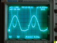
This is a scope shot of a screen driven 6CB5 sweep tube's plate and screen voltage. It is from some early screen drive experiments done about 12 years ago. The test amp is making 130 watts into a RESISTIVE load. Plate supply voltage is 550 volts, load impedance is 2500 ohms. This amp clips hard at about 150 watts. It is making about 3% THD here with some mild clipping seen on the load resistor. No feedback is used.....that only makes matters worse!
The screen (drive) voltage is the (bottom) clipped sine wave. Scale is 50 volts/div. Zero volts is the second graticule line from the bottom. G1 is connected to a small negative voltage, so that any screen voltage below zero cuts the tube fully off. The plate voltage is the other trace. It is fed to an external voltage divider to avoid blowing up the scope. Scale is 100 volts/div.
The first picture shows operation at 80 watts. The drive voltage goes from about -5 volts to +180 volts. The plate is pulled down to about 90 volts and the THD is around 1.5%
The second picture shows operation at 130 watts. The drive goes down to about -20 volts, and up to about +200 volts. The plate actually swings about 10 volts NEGATIVE briefly before settling near +50 volts, then shooting for the sky at about 1200 volts.
Cranking the amp near 150 watts output causes overload to the screen grid, and blown mosfets in the driver. It was not attempted long enough to get a good scope picture.
Attachments


- Home
- Amplifiers
- Tubes / Valves
- EL34 data sheet - operating points