
More info and some references in the attached.Chances are that the aluminium electrolytic capacitor I used in the RTZ shift register DAC also has 1/f noise on its leakage current. I never measured it, but I can't think of any reason why it would be unique to tantalum capacitors.
Attachments
"The value of the noise intensity at f= 2 Hz can be used as an indicator to predict the individual lifetime of an aluminium electrolytic capacitor."
A bit like switching it on and off continuously 🙂
A bit like switching it on and off continuously 🙂
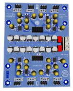
I've decided to make a smaller pcb, in my default small size (ca. 80x60mm).
The following are omitted:
The following are added:
The following are omitted:
- microcontroller (ATtiny85): I plan to use the DAC mainly in HW mode, but if needed, I2C pins are available for external controller.
- clock: I will design an extra universal clock pcb with buffered outputs and reclocking gates, similar to "IanCanada's".
- 2 GPIO pins, beacuse of shortage of space. The DSD and SPDIF functions I will not use anyway...
The following are added:
- onboard footprint for vregs: AVDD, DVDD and VCCA for LP5907 or ADP151 ICs.
Attachments

Last edited:
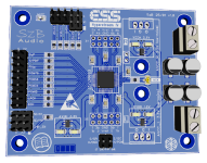

I give a short description of the design. The main goal is to create an affordable, simple but flexibel and very good multichannel DAC system, especially for stereo active speaker systems (like the open baffle LX521 ect...). Earlier I was not a big fan of ESS DACs because of more reasons. The new Hyperstream IV serie brings some benefits indeed, so why not give a try? Some key points:
My design as you see contains three main PCBs:
What else is needed to become an operational device:
If you wish I can draw a system block schematics for a better visual understanding.
- The ES9017 and 9027 are both available in "leg" version (QFP package, DIY friendly!) and are pin compatible with each other (THD+N/DNR: 110/120dB vs 114/124dB)
- They can work in hardware mode, so if you don't need any extra options (volume control, ect.) you can use it simply with setting up some jumpers
My design as you see contains three main PCBs:
- the DAC board with all the input/output pins and jumpers, onboard digital regulators
- the Filter board placed directly beneath the DAC, for current/voltage conversation and filtering, as recommended in the datasheet (very special topology!)
- the Clock board with ultra-low jotter oscillator and clock puffer, integrated voltage regulators. It is possible to disable both regulators or even the oscillator and connect external ones.
What else is needed to become an operational device:
- a multichannel digital receiver with I2S outputs (e.g. DIYinhk)
- mains transformers and voltage pre-regulators, especially +/- supply for the opas (I have in my sortiment!)
- 2 pcs of low-noise analog voltage reference regulators (e.g. LT3042, I have in my sortiment!)
- Optional: Micro-controller with IR-receiver and display (e.g. Arduino Nano, I have in my sortiment!)
- Chassis, wires, connectors, ect.
If you wish I can draw a system block schematics for a better visual understanding.
Did you know that ESS made also their own regulators for suppliyng dual AVCC rails of ESS dac chips ? ES93122 pcs of low-noise analog voltage reference regulators (e.g. LT3042, I have in my sortiment!)
https://www.esstech.com/products-overview/voltage-regulators/The ES9312 is a 2nd generation dual ultra low noise linear regulator optimized to supply the reference voltages for ESS Technology’s SABRE® DACs, ADCs, CODECs as well as applications that require very low noise voltage references. The ES9312Q provides several unique features including ESS DAC calibration, internal fixed mode presets, and multiple warnings indicators. The ES9312 small 3x3mm package is ideal for minimizing board area and cost-effective.
Yes of course. The ES9312 is comparable or slightly worse to the LT3042. The ESS chip has a QFN package, not easy to solder at home!
The only benefit could be, that the ESS regulator can be coupled with an internal "calibration" (about 50-100k) resistor of the DAC chip. But what this "calibration" means in the real world, is not documented and the ESS distributor could not answer this question either. So, in the first run, I see it only as marketing... BUT: I've made a GPIO pinout (CalRes) in the near of the AVCC regulators, so if you wish you can develop a daughter-pcb with this IC...🙂 Just for comparison...
The only benefit could be, that the ESS regulator can be coupled with an internal "calibration" (about 50-100k) resistor of the DAC chip. But what this "calibration" means in the real world, is not documented and the ESS distributor could not answer this question either. So, in the first run, I see it only as marketing... BUT: I've made a GPIO pinout (CalRes) in the near of the AVCC regulators, so if you wish you can develop a daughter-pcb with this IC...🙂 Just for comparison...
Attachments

How is solved the problem of the volume pot ?
All the multichannel DAC w/o volume pot make unhappy their owner
All the multichannel DAC w/o volume pot make unhappy their owner
While I haven't tried ES9312 its predecessor ES9311 (with better specs) is the worst voltage regulator I've ever used. High 1/f noise and very fragile. LT3042 is lightyears ahead of ES9311.The ES9312 is comparable or slightly worse to the LT3042.
IIRC, the calibration thing was supposedly if using multiple ESS chips to get more than 8-channels. There is no guarantee each dac chip will produce exactly the same analog output for a given digital input. Again IIRC, calibration can turn down the output level of the louder dac chips by pre-attenuation before the internal volume control, or something more or less like that.
If you want a volume pot (or IR remote), you need a Microcontroller via I2C bus, like Arduino. It's not a problem at all, I have it too...How is solved the problem of the volume pot ?
All the multichannel DAC w/o volume pot make unhappy their owner


Apparently posts are removed without any message in normal non vendor threads? Is this a new thing? Or is this going to be a commercial project?
If not this would be censorship.
If not this would be censorship.
"Apparently posts are removed without any message in normal non vendor threads? Is this a new thing? Or is this going to be a commercial project? If not this would be censorship."
Please? I have no idea, please ask the admins...
Please? I have no idea, please ask the admins...
Well it was this thread and normally when things are corrected/edited by admins on request of the thread owner one receives a message. Posts disappearing just like that is unusual to say the least.
Or is it forbidden to say something about a 14 module DAC? 🙂
Or is it forbidden to say something about a 14 module DAC? 🙂
It has happened before, see https://www.diyaudio.com/community/...makes-nos-sound-different.371931/post-6815541 for an example.
- Home
- Source & Line
- Digital Line Level
- ES9017/27 DAC design