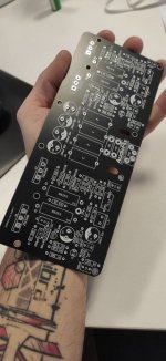
Been working on a stereo PCB based on the Project 3A from Rod Elliot, i'm here asking you guys what do you think about this layout.
P.S. Since i can't find the exact BJTs used in the original Project, i wonder if i could use a couple of 2SC5200 and 2SA193.
P.S. Since i can't find the exact BJTs used in the original Project, i wonder if i could use a couple of 2SC5200 and 2SA193.
Attachments

The drivers/VAS are not positioned correctly. Maybe you could start by reading Rod's indications concerning their placement and/or purchase his PCB.
The routing seems excessively intricate for a relatively simple circuit: Rod's layout is much simpler and single face. I used 2SC5200 & 2SA1943 in my P3A.
The routing seems excessively intricate for a relatively simple circuit: Rod's layout is much simpler and single face. I used 2SC5200 & 2SA1943 in my P3A.
Last edited:
There are many threads here about attempts to design and make DIY P3A PCBs to save a few dollars. Most so far, have been pretty poorly conceived and many designers seem to misunderstand the basics of good layout, even to the location of a driver transistor that needs to be in thermal contact with the bias control element Q9 (the Vbe multiplier transistor)
The threads are easily searched with our new forum software and though there are plenty of efforts that should be avoided, Alex MM's professional design appears to be among the best, though I haven't personally built or tested it. There's no need to re-invent the wheel here, just use the valuable info and resources already examined, proven (or amended if there are errors) and made available here.
The threads are easily searched with our new forum software and though there are plenty of efforts that should be avoided, Alex MM's professional design appears to be among the best, though I haven't personally built or tested it. There's no need to re-invent the wheel here, just use the valuable info and resources already examined, proven (or amended if there are errors) and made available here.
Last edited:
The drivers/VAS are not positioned correctly. Maybe you could start by reading Rod's indications concerning their placement and/or purchase his PCB.
The routing seems excessively intricate for a relatively simple circuit: Rod's layout is much simpler and single face. I used 2SC5200 & 2SA1943 in my P3A.
I've already drawn the original Layout:
Attachments


You mean you can't find TIP2955 and 3055?Been working on a stereo PCB based on the Project 3A from Rod Elliot, i'm here asking you guys what do you think about this layout.
P.S. Since i can't find the exact BJTs used in the original Project, i wonder if i could use a couple of 2SC5200 and 2SA193.
Or BD139/140?
Seriously?
I can't find any MJL21193 and MJL21194 😉You mean you can't find TIP2955 and 3055?
Or BD139/140?
Seriously?

Much better 👍I've already drawn the original Layout:
Make sure Q6/Q9 and Q13/Q10 are in contact or even strapped together.
As I wrote before, 2SC5200/2SA1943 work very well in P3A.
An excellent amp, by the way.
Much better 👍
Make sure Q6/Q9 and Q13/Q10 are in contact or even strapped together.
As I wrote before, 2SC5200/2SA1943 work very well in P3A.
An excellent amp, by the way.
Thanks!
I'm gonna send Gerbers to JLC right now!
Member
Joined 2009
Paid Member
If it is of help, I made a pcb design for a circuit that was evolved from Rod's P3A. The Gerber files are in this thread:
https://www.diyaudio.com/community/threads/tgm8-an-amplifier-based-on-rod-elliot-p3a.245619/
I can't say off the top of my head if it can be used for the baseline P3A because I did improve on the circuit (a lot) but I suspect it can be used and it will take care of the thermal management etc.
https://www.diyaudio.com/community/threads/tgm8-an-amplifier-based-on-rod-elliot-p3a.245619/
I can't say off the top of my head if it can be used for the baseline P3A because I did improve on the circuit (a lot) but I suspect it can be used and it will take care of the thermal management etc.
Much better 👍
Make sure Q6/Q9 and Q13/Q10 are in contact or even strapped together.
As I wrote before, 2SC5200/2SA1943 work very well in P3A.
An excellent amp, by the way.
Added a PSU PCB
Attachments


My apologies I confused P3 and P3A.You mean you can't find TIP2955 and 3055?
Or BD139/140?
Seriously?
I actually bought quads of TTA and TTC versions for a remake of the P3, without really knowing if they would work
JLC PCB, i think it's one of the best value for moneyNice job Ciro82 👍.
Where did you get them made?
Auguri!

@jacques antoine i would like to build 2 boards to make a 4 channel Amp, but i'm out of BC546, what substitute could i use?Nice job Ciro82 👍.
Where did you get them made?
Auguri!
Something like BC547 - BC550 or?
- Home
- Amplifiers
- Solid State
- ESP P3A