Hi X et al,
I hooked up the instant off modules (IOM) in preparation to wiring them up to the RTRSSR modules. AC was checked entering the IOM's and decided to check the voltage and polarities on the molex outputs. I got the polarities and the voltage was 0 Volts on both boards. Is this normal, or have I wired the modules wrong .
.
Thanks for the help, see pic attached.
MM

I hooked up the instant off modules (IOM) in preparation to wiring them up to the RTRSSR modules. AC was checked entering the IOM's and decided to check the voltage and polarities on the molex outputs. I got the polarities and the voltage was 0 Volts on both boards. Is this normal, or have I wired the modules wrong
.Thanks for the help, see pic attached.
MM
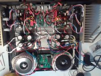
I thought I had er built this time. I powered up with a variac & dim bulb tester (100W bulb). With everything hooked up I watched in wonderment as all the led's lit up from the soft start, the psu the amp boards, the low capacitance psu, and the RTR SSR modules, no magic smoke. Dim bulb teaster showed only a faint glow at V> 100V. Pic below

I had checked the bias earlier, so I hooked up a couple of speakers and I received glorious sound, but only from one channel. I started visually checking things on the problem non channel, but everything looked good. The bias is good on the channel with no sound. I tried the following :
I swapped out speaker, no difference. Swapped speaker wires, no sound from problem channel.
I unhooked the low cap psu which turned off the RTR SSR modules on the problem channel, and ran wire to the speakers from the amplifier, still no sound from problem channel.
Tomorrow, I will try to swap the inputs.
Any other trouble shooting techniques I can try ?
Thanks,
MM
Usually when bias current is good and there is no sound the problem is that input connection is not good (open) or reversed polarity. If you have speakers connected and touch the input pins with your fingers the speaker should pick up a hum from you acting as an antenna. Is there any response or sound at all?
Please check for signal continuity from RCA +ve pin to the PCB input Molex KK pin 1 (on the left looking at the board from the front).
Please check for signal continuity from RCA +ve pin to the PCB input Molex KK pin 1 (on the left looking at the board from the front).
Last edited:
zman01, all led's lit.
X, no response from the finger test. I probed the the area between the rca input and the molex input to the amp:
I have continuity between both the + and gnd of the rca inputs and the + and gnd in the male molex module.
I have continuity between the rca gnd and the molex gnd pin on the amp board.
I have no continuity between the rca + and the molex + pin/in on the amp board.
I have attached a pic of the underside of the amp board. The molex tab is solidly attached. Surrounding soldering looks good also. Is it possible to have a bad pin in these molex components?
Thanks,
Oops missed that
Looking at the PCB there seems to be several areas where the solder mask has been scraped off or damaged, look at these areas and check for solder bridges. Use eye magnification, and clean the flux off so you get a better look. Cleaning the flux will also show you areas where you need to retouch with the solder iron. (Cold joints)
Looking at the PCB there seems to be several areas where the solder mask has been scraped off or damaged, look at these areas and check for solder bridges. Use eye magnification, and clean the flux off so you get a better look. Cleaning the flux will also show you areas where you need to retouch with the solder iron. (Cold joints)
Will do Vunce. Thanks for the help. One quick question before I begin to work on the board.
The rca cable on the good input jack is nice and tight to push on /pull off. The rca cable for the bad side hardly has any friction to push on/pull off.
Do you think it may not be making proper contact with the positive post of the input jack?
Remember that these boards were producing music before, and I have not changed anything on the board except transistors.
I may put the amp board back in, and power up with better rca cables that fit snug to see if that solves the problem.
Your thoughts
Please check red circle areas for solder bridge. Use continuity check between the two adjacent pins. Touch up with soldering iron and flux. It appears your iron may be under powered as the fillets are not smooth and wetted. I use a 70w iron with a big fat chisel tip. Real Pb solder with rosin core.
That’s a problem. Looks like a bad connector or wire.I have no continuity between the rca + and the molex + pin/in on the amp board.
Vunce, tried reversing cables before, no difference
X, using a Hakko FX-888 70 W iron with a chisel tip. May be time for a new tip.
By saying a bad connector, you are referring to the molex connector, specifically the + post. I have continuity from the rca jack to the harness for both + & gnd, and I have continuity from the rca jack to the gnd pin on the input. I just do not have continuity to the + pin on the input.
If it was the + wire from the rca jack that was faulty, I would not have continuity at the end point of the harness. So I do not think it is the wire. Maybe I need to solder in a new molex connector, or possibly just solder wires directly to the input & gnd on the amp board.
I will fire up the iron and clean up the board and solder joints as much as possible.
Still battling C-19 symptoms, so I am unable to scoot to my electronics store and pick up some more molex crimp contacts good for 16-18 ga. From removing / replacing amp module so much, one of my Vbe multiplier wires popped out of the harness. I think I am going to remove the 3 pin connector and solder these directly to the amp board.
Thanks for the help
MM
I spent some hours on the weekend reflowing solder joints and cleaning up the board on the channel that is not working. I checked continuity all over the board, and it checks out really well. So I fixed up my wiring on the BD139G transistor and put it back together:
I did not receive any sound from the speaker, but I did receive a hum from the speaker using the finger test.
Should the next step be to twist the input wires 180 degrees and see what happens?
I did not receive any sound from the speaker, but I did receive a hum from the speaker using the finger test.
Should the next step be to twist the input wires 180 degrees and see what happens?
Hi Myles,
Good work on the cleanup - please show us photos. Now that you get hum when touching the terminals, I think it should play music. Connect the Molex from the other channel.
A continuity check should show connection from the RCA jack to the Molex pin. If not your wire, or connectors, or both are bad.
Good work on the cleanup - please show us photos. Now that you get hum when touching the terminals, I think it should play music. Connect the Molex from the other channel.
A continuity check should show connection from the RCA jack to the Molex pin. If not your wire, or connectors, or both are bad.
Ricky Ray and X,
I had to hard solder the BD139 to the board. To gain access to the bottom of the board for photo's, I will have to unbolt the BD139 from the NMFet. I will do this if your suggestions from post #1037 do not work. I will let you know tomorrow what happens.
Thanks for the help,
MM
I had to hard solder the BD139 to the board. To gain access to the bottom of the board for photo's, I will have to unbolt the BD139 from the NMFet. I will do this if your suggestions from post #1037 do not work. I will let you know tomorrow what happens.
Thanks for the help,
MM
X,
1. Connected input from the working channel to the non working channel and music played from the correct speaker. This is good. Shows no problem with molex connector.
2.Connected the input from the non working channel to the working channel and received no sound. When I disconnect the gnd wire from this test I receive hum, attach again and no sound.
3. Checked continuity from rca to wiring harness on the non working channel. Continuity on both + and gnd wire from rca input to end of molex harness.
4. Checked continuity from rca input to molex pins. Continuity on gnd from rca to molex gnd pin. No continuity from rca + pole to molex + pin
So #1 points toward no problem with molex connector on non working channel and suspect input wiring.
#2 points toward to suspect input wiring.
#3 points toward no problem with input wiring to end of molex harness.
#4 point towards bad molex connector on + side.
Maybe the suspect wiring is influencing points #3 and #4 and need to be corrected. I am inclined to agree with point #1
Thoughts?
- Home
- Group Buys
- FH9HVX - Budget Conscious 100w Class AB for Lean Times