Oh wait, never mind my post #19, now I see what you did in #17 (though what I said still applies to earlier schematics), and ... this is kinda bizarre. The "feedback" resistor R150 now does nothing - it basically has no signal voltage on either side. When the top half has an increase in voltage, the bottom half has a decrease in voltage, and they cancel out through the resistors to that feedback path.
So you've got one output driven by the mostly-NPN path and the other output by the mostly-PNP path. These two outputs are halves of what was once a single output stage, but they don't tie together for an output, they go to two separate outputs.
This 'works' but may still be too dependent on transistor betas/Hfe's (the emitter resistors moderate this, but it' a headache going through four transistors figuring out the bias/output voltage), and the peak-to-peak output level is limited to half the supply voltage. My feeling is everything to the right of the phase splitter needs to be redone. Make it two separate, independent (and identical, while you're at it) amplifiers, each powered from V+ and V-.
The purpose of a balanced line driver is:
As said: To drive two lines in a balanced way: That is, same voltages, same outputs impedance.
That said, in audio the usual solution is:
From the asymetrical output stage that is typically an opamp output with 47 ohm outputing out+.
Add an opamp to invert the signal to make out-.
That is: Half a NE5532, two 10k resistors, a 47 ohm resitor to provide out-.
With some 22pf across the feedback 10k and most important: a 0,1uF ceramique cap across V+ V-.
Of course, it doesn’t look symetrical inside, but who will know but you, what matters is symetry outside.
An XLR socket with out+ and out- at pin 2 and pin 3 with chassis at pin 1.
Last edited:
Thank you for your reply. Yes I have seen this trick while researching the subject, but this is dependent on the source impedence which in my case can vary. For example my first use case is a phono preamp which has discrete push-pull emitter follower output.
I've come up with a discrete version that sort of work but it would be dependent on transistors and resistors matching and distortion is high-ish. The dedicated balanced driver ICs offer the best performance but are high priced.
So I'd go with the dual op-amp implementation like mentionned in post #15, a voltage follower buffer feeding into a 6dB inverting gain stage for the complement. This would be independent of source impedance. The 22pF and 100nF capacitors will be added to the basic circuit below. 0.1% low tempco resistors might be needed.
These are for compensation, correct? I believe ceramics can be used there as well as they won't pass audio signal?22pf across the feedback 10k

Fine.
Add two 47 ohm at the outputs. This gives protection in case of a short and it swamps the output impedances at this same value regardless of the opamps output small impedances.
Do not leave the input floating, it needs biasing.
Add two 47 ohm at the outputs. This gives protection in case of a short and it swamps the output impedances at this same value regardless of the opamps output small impedances.
Do not leave the input floating, it needs biasing.
Here it goes. The inverting stage provides the 12dB boost for pro level. Actual opamps won't be TL072 like in the sim but "hifi" rated NJM2068D or LM4562NA.

Thank you for your advice. There is already a coupling capacitor at the output of my phono preamp but I will add it to the line driver circuit as an option for other use cases.
But may I ask, why not the output caps? I see them fitted in most of the circuits I see and in application notes. For example from Jensen technical note AN-003 "Interconnection Of Balanced And Unbalanced Equipment" which I use as a reference :

But may I ask, why not the output caps? I see them fitted in most of the circuits I see and in application notes. For example from Jensen technical note AN-003 "Interconnection Of Balanced And Unbalanced Equipment" which I use as a reference :
Why not balancing transformer? Its used in studio often.
My very old germanium sparta studio phono preamp has it.
Dartzeel power amp has it on input.
I used balancing transformer on every F1J amp with great results.
Transformers are small, for line level, and have pleasing distortion profile. No power supply required.
My very old germanium sparta studio phono preamp has it.
Dartzeel power amp has it on input.
I used balancing transformer on every F1J amp with great results.
Transformers are small, for line level, and have pleasing distortion profile. No power supply required.
It is an option I can use as I have a trio of them somewhere in boxes. One pair will probably end at the input of an upcoming tube amp.
This line driver project is formative though and will serve to evaluate both avenues in listening tests.
The op-amp option is a lot cheaper, although I did see line level offerings by Edcor who are worth considering.
This line driver project is formative though and will serve to evaluate both avenues in listening tests.
The op-amp option is a lot cheaper, although I did see line level offerings by Edcor who are worth considering.
IMO, there is no need for output caps. They put them to make sure of no DC. Some DC is not that bad, it is eaten by any decent following line equipement right at its input. Little differental DC ( say 20mV ) is no issue, some common mode DC ( say 1V ) is just a small loss in headroom, no trouble on sound quality.But may I ask, why not the output caps? I see them fitted in most of the circuits I see and in application notes. For example from Jensen technical note AN-003 "Interconnection Of Balanced And Unbalanced Equipment" which I use as a reference :
Furthermore, quite low output impedance leads to high value caps, hence electrolytics that have bad reputation. No electrolytic in the signal path is a rule, I use to follow.
Conversely, cap at the input is a must to get rid of any received DC. Because of a quite high input impedance one can use a film cap for enough low frequencies.
I had a look at the Jensen AN-003. I do not understand their electrolytic caps at the outputs, they show them, on and on, without any explanation about it.
No doubt they know about their audio transformers and business. But !
A reference I do trust is ESP by Rod Elliot. Tons of good electronics, simple and well explained with humour at debunking audio myths.
https://sound-au.com/articles/balanced-io.htm#s2
No doubt they know about their audio transformers and business. But !
A reference I do trust is ESP by Rod Elliot. Tons of good electronics, simple and well explained with humour at debunking audio myths.
https://sound-au.com/articles/balanced-io.htm#s2
I would use the output caps for sure. Disliking electrolytics is not a valid reason to remove them. All this messing around to produce a balanced output and you end up with a small DC residual? Not in my gear. If it makes you feel better, use a film cap, and do the math on the appropriate value to use. No one says the 100k resistor is the 'right' value either. Even 1M could work, which helps the capacitor sizing.
Those Jensen JT-11 output transformers are the best solution. Superior CMRR than anything you will build, and robust/bulletproof as you can get. No need to worry about compensation, gain margin, stability.
Most importantly, they could care less what type of equipment you are feeding into - perhaps it does not have a DC blocker. No problem with a transformer.
Jensen Transformers worries about stability of JT-11 circuits so much, that they manufacture and sell a transformer compensator product called JT-OLI-2 which "prevents oscillation and instability". The very first figure in the JT-11 datasheet calls for a JT-OLI-2 in series with the JT-11.Those Jensen JT-11 output transformers are the best solution. Superior CMRR than anything you will build, and robust/bulletproof as you can get. No need to worry about compensation, gain margin, stability.
Most importantly, they could care less what type of equipment you are feeding into - perhaps it does not have a DC blocker. No problem with a transformer.
_
Attachments

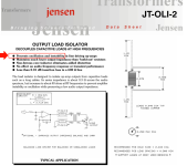
Isn't that simply a kind of snubber? I wonder if one could just use its equivalent circuit as a discrete 3.7uH miniature RF inductor and 39R resistor in parallel for the same effect.a transformer compensator product
If so I would put it as an optional path on this project's pcb to allow usage of a transformer instead of the big output 'lytics. This would provide yet another avenue to try out.
Don't blame the transformer, blame the op amp.Jensen Transformers worries about stability of JT-11 circuits so much, that they manufacture and sell a transformer compensator product called JT-OLI-2 which "prevents oscillation and instability". The very first figure in the JT-11 datasheet calls for a JT-OLI-2 in series with the JT-11.
_
Still the optimal solution for all the challenges at hand.
Yes.I wonder if one could just use its equivalent circuit as a discrete 3.7uH miniature RF inductor and 39R resistor in parallel for the same effect.
Transformers work best (lowest LF distortion) when driven with zero ohms source impedance but this is at odds with the capacitive load intolerance of pretty much any opamp (except some very special types) and also discrete amplifier circuits.
The L//R breakout is a simple and well-working solution.
NP said that one of the Zen iterations, the Balanced Zen Line Stage, would make a very good SE to Balanced device. Maybe look at it for inspiration.
The circuit amplifies a differential input to a differential output. Given a single input, it will amplify it into a balanced differential output, and is useful to convert unbalanced signal to balanced, either because you wish balanced operation or because you wish to convert a conventional stereo amplifier into mono bridged operation.
- Home
- Design & Build
- Electronic Design
- First time designing single-ended to balanced line driver