

When can we expect to see Babelfish SIT-5?
I already have/had something similar, early iteration of Babelfish XA252 (SIT), which I abandoned, wasn't too happy with parts choice, even if I was happy with performance
I'm not Pa, having dozen grocery bags full with Toshiba TO92 JFets.....

How about making just the back-end to connect to the DIY Front End 2022?
And adding to my list of demands, please consider attending BAF 2025.
And adding to my list of demands
, please consider attending BAF 2025.
I already have/had something similar, early iteration of Babelfish XA252 (SIT), which I abandoned, wasn't too happy with parts choice, even if I was happy with performance
I'm not Pa, having dozen grocery bags full with Toshiba TO92 JFets.....
What... no more Macho SIT? You gave up on it? You know it did sound very good!
So, how about the Biggvs Dickvs SIT? The mythical 100 wpc SIT. Is that done too?
What... no more Macho SIT? You gave up on it? You know it did sound very good!
So, how about the Biggvs Dickvs SIT? The mythical 100 wpc SIT. Is that done too?
what's wrong with reading, Boy?

early iteration, which I abandoned, and nobody exactly seen that
even if I probably posted schm somewhere, maybe even pic of populated pcbs
Many many THANKS, Nelson!
"
Hi Gerd,
Feel free to post this.
There are two resistors, what we will call R1 is between the Source
pins of the Fets. The other, R2 is in series with output cap.
Depending on the values of the N channel and P channel Vgs and
any bias voltage between their Gates we adjust R1 (or the bias voltage)
for the DC bias current we want. That's easy to determine and deal with.
R2 alters the P channel device's AC contribution to the output and is used
to adjust the load line experienced by the N channel device.
We determine the ratio of contribution by measuring the AC output voltage
across a resistive load (typically 8 ohms) and the AC voltages across R1 and
R2. The first measurement allows calculation of the total output current, and
then determine currents through R1 and R2.
The sum of R1 + R2 AC currents is the contribution of the P channel device
and dividing it by the total output current gives the percentage of contribution
of the P channel device.
The distortion character of the output is altered by this ratio. On the one hand
R2=0 gives straight undegenerated push-pull. On the other hand nonzero R2
moves toward single-ended dominance by the N channel Fet.
You can get this effect by other means, but this is the easiest to adjust -
you set the DC bias with R1 and the AC ratio by R2 seperately.
🙂"
I asked, he answered!
🙂
Last edited:

Spice says the currents through Nelsons R1 and R2 are anti phase so they tend to cancel when they are equal.....and there is remaining amount when they are not equal that can be easily done with a resistor change to the second output cap.
Am I wrong?
It took me one day to see this.... do not laugh!
🙂
Am I wrong?
It took me one day to see this.... do not laugh!
🙂
I did some sim and saw they are not anti-phase. They are same phase. P-Mosfet "contributes" 25%(power or current?) of the total (power or current?)
In the past I tried amplifiers and lithium but at a much lower voltage. 🐔
Today I got a bit of courage and connected a 3kw battery to the amp 🙂)

Yes.. big fuses, bms.. protection first 🙂)
Today I got a bit of courage and connected a 3kw battery to the amp 🙂)
Yes.. big fuses, bms.. protection first 🙂)
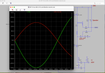
I went back to my Spice and called the resistor between the sources R1 and the resistor going to the second output cap R2.
When I look at the currents of R1 an R2 they are antiphase. I lifted the R2 current a bit for better comparison.
And yes the current through the caps are in phase, but this was not my claim.....
:--))
So R1 and R2 do not simply add with their full values....
When I look at the currents of R1 an R2 they are antiphase. I lifted the R2 current a bit for better comparison.
And yes the current through the caps are in phase, but this was not my claim.....
:--))
So R1 and R2 do not simply add with their full values....
Attachments
Last edited:
The problem might be due to the resistor orientation, i.e. the direction of the arrow for the resistor in the LTSpice schematic. To properly compare the rerlative phase, the arrows for both R1 and R2 should point into the common node that connects to the PFET drain.
- Home
- Amplifiers
- Pass Labs
- First Watt SIT5