Fixing a Marantz SR8500 in protection mode.
Hi guys
As the title states, I have gotten my hands on a Marantz SR8500 which is going into protection mode on start up. Sometimes, but not always the display will show Error POW5, whichs as far as I understand can be caused by just about anything, on any board, failing.
The thing is, that when I first brought it home I tried to power it up on the kitchen table to see how it behaved. And then it just started right up and I was able to navigate menus, choose input etc. Well that was easy I thought, and moved it to the livingroom, to try and hook up some speakers (FL + FR).
I was out of luck, however and the amp started going into protection mode again. Disconnecting the speakers does not help. Of course I curse myself for not trying to power up the amp after I moved it, but before connecting the speakers.
I've since tried to leave the amp disconnected for several days and power it up again, but it still goes into protection mode.
I have now taken it apart and started measuring resistances etc. The speaker channels look fine (it uses sanken sap17 integrated transistor and emitter resistor, so I don't know how to test them just using my dmm, afaik it's not possible). So for now I am focusing on the power PCB. I have identified four 10k ohm resistors (R611, R612, R616 & R617) which only measures to 7.40k ohm, where as the identical resistors (R613. R614, R615, R619, R620) all measures to ~9.85k ohm. Would that be enough to force the amp into protection mode? And/or can you give me some ideas on what to look for.
Service manual is here http://diagramasde.com/diagramas/audio/Marantz%20SR7500,8500%20%28PS7500,8500%29.pdf
Thanks in advance
Last edited:
Something wrong here.I downloaded the manual, no SANKEN to find here.
There is a R611 and R612 in one of the P-Amp's but 470 Ω, not 10k.
Mona
There is a R611 and R612 in one of the P-Amp's but 470 Ω, not 10k.
Mona
You can't measure resistors in circuit as a general rule because of other interactions. You need to isolate one end. I'm sure your 10's will be fine.
Most transistors fail by going short circuit (typically from C to E) which would be easily checkable on DVM.
You may get lucky and find this is just an intermittent or dab connection somewhere, particularly with it first working.
Most transistors fail by going short circuit (typically from C to E) which would be easily checkable on DVM.
You may get lucky and find this is just an intermittent or dab connection somewhere, particularly with it first working.
Hi Mona
Thanks for getting back. Be sure to look on the right parts list (for the right model and board) the numbers are reused across the boards. The one I'm looking at is the Power pcb.
I got confused by that as well.
However i suspect that the different measures is due to measuring in circuit.
But any pointers on where to look will be most welcome 🙂
Thanks Mooly
(Wrote the first reply before seeing yours)
I'm sure you are right about the resistors, maybe i should just try and put the whole thing together again, and see if that does the trick.
Thanks again to both of you and merry Christmas
(Wrote the first reply before seeing yours)
I'm sure you are right about the resistors, maybe i should just try and put the whole thing together again, and see if that does the trick.
Thanks again to both of you and merry Christmas
So no Amp-module but discrete transistors.
There is a protection for to much current in the power-amp and aso for to much DC on the output.
If aprotection is activated the amp goes in standby.
With R816 short cicuited there is no overcurrent protetion.
Short circuiting C809 prevents all protection exept over temp.
First R816 ,if then no standby, at least one of the power-amps draws to much current.
No difference after R816 short, then C809.if now no standby there is DC on the output somewhere.
Still no result, the over temp. resistor, one of the connectors or the controller (DSP-board) doesn't function.
Here are the part of the schematic and AMP PCB with indications.
Good luck and merry X-mas
Mona
Attachments
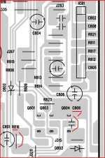

Ok, so I put the whole thing back together, and tried short circuiting first r816, then c809. neither prevented the amp from going into standby.
Meaning that
> temp. resistor, one of the connectors or the controller (DSP-board)
is malfunctioning. Will there be any risk in bypassing the over temp. resistor in order to measure som voltages?
My best guess is still a bad/cold solder somewhere, given that I was able to power on the receiver when i first tried. Another thingm though is that when I managed to power it on, it was quite cold. I did tried to leave it over night in our utility room, which is unheated, to no avail.
I guess the next step will be to have a look at the DSP board again. to see if I can find anything suspicious.
Rather reassuring, porbably nothing wrong with the Amp's.
That leaves overtemp.circuit and µC.
Temp.sensing is done with an PTC resistor connected a CN82.If it make no contact the alarm goes the same way as for the amp fault, So shorting C809 prevents that to.
Bypassing the PTC prevents a overtemp.alarm, but a defective Q803 can still give a overtemp. signal.
Mona
- Status
- Not open for further replies.
- Home
- Amplifiers
- Solid State
- Fixing an Marantz SR8500 in protection mode.