Adding the ceiling image
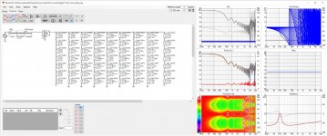
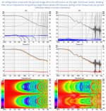
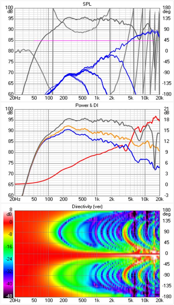
Vituix has a hard limit of 64 drivers. After being reminded of that, I tried a 21x3 element array. The response of that looked broken. I dropped 7 drivers off each end of the array and things started to look reasonable. Think of this array as a 16 element array with floor and ceiling image drivers (and one extra) in a low ceilinged space.
First the un-equalized array with a flat driver model (i.e. point source)

Plugging in the TC9 directivity data and equalizing to the 6th octave smoothed room response curve:

While these results look reasonable as far as they go, I've noticed undue sensitivity to microphone elevation and listening distance, which in no way corresponds to reality. Enough said for now.
Vituix has a hard limit of 64 drivers. After being reminded of that, I tried a 21x3 element array. The response of that looked broken. I dropped 7 drivers off each end of the array and things started to look reasonable. Think of this array as a 16 element array with floor and ceiling image drivers (and one extra) in a low ceilinged space.
First the un-equalized array with a flat driver model (i.e. point source)
Plugging in the TC9 directivity data and equalizing to the 6th octave smoothed room response curve:
While these results look reasonable as far as they go, I've noticed undue sensitivity to microphone elevation and listening distance, which in no way corresponds to reality. Enough said for now.
Attachments
still using linear phase LR like beforeIn all honesty I think this FR plot is pretty close to reality. Did you apply some sort of absorption in the reflection properties? I'd believe we wouldn't get a true floor reflection but that it would be somewhat reduced in level. Not sure how much it would be reduced though.
Not sure why the vertical directivity is upside down from what I expected, but that may be due to the lengthened array with floor mirror? (missing the ceiling, thus having the symmetry (mid array) fall below the zero line)
What does it look like without floor reflection but with the 1m height position for equalising?
I think for a seated listening preference that shaded result looks pretty interesting too.
If one were to prefer a listening seat only setup it could prove to be worth investigating this further.
Can you show the other graphs belonging to this one?
And was this one done with passive means or linear phase LR like before.
Yes I thought the curve looked pretty realistic too. But it may have an unrealistic microphone position sensitivity; the floor and ceiling image model did.
And I agree re' pursuing further for a seated only configuration but I've realized that might frequency shading constraints have to extended to include cutting off a driver before its first order floor or ceiling reflections exceed 90 degree phase shift. I doubt that can be met for a floor to ceiling array but looks doable for something half that height.
I don't model any absorption on floor and ceiling. Depending on construction, the floor could have pretty high reflectivity; ceiling not so good. But Vituix is far from a room simulator so we just get very rudimentary room response. I think in Kimmosto's mind, its just there to illuminate potential boundary support and interference issues.
Is this what you meant re' the other graphs?
Attachments
No, thank you for the interest and collaboration. Its not a question of easy; its the imperative next step. I was at first discouraged when I realized I had to worry about reflections coming back more than 90 degrees out of phase. Now I see that if the HF section is close enough to the floor that can be managed. I might have to ask you to get a recliner, though. So I will work it out and enjoy doing so, especially if it works ")
It has always been my goal to work together to advance the array together. One of the many reasons I do share what I do. It has worked well with our growing group of line array users I think. Helping others has also helped me understand the array more than only having my own data to play with.
I'm always interested if we can up it a notch. So far I have had a lot of different renditions of my DSP, one of my goals was great sound in the sweet spot, good sound all around. Even if that meant giving up some of the things that made the sweet spot even more thrilling.
Basically, that's what I have with an unshaded array. Going shaded might improve upon seated listening experience again, but influence perception everywhere else. I need to think long and hard if that's something I would be willing to do. But simming it to "see" its potential is harmless enough. Still it won't be an easy choice to make.
I might be willing though. This year my living room will get a make-over. The hard (and reflective) ceiling I have will be gone and make room for a more absorbent material. I will be without arrays for a while and have them stored in the garage. That will be a good moment to think long and hard how to proceed.
Last edited:
A 1" thick acoustic ceiling tile should be sufficient to justify ignoring ceiling reflections in the frequency shading calculator.
I redid the spreadsheet to include the floor image drivers and reduce the microphone height. Ignoring the floor reflections contribution, the spreadsheet shows the top driver can play up to 454 Hz without combining destructively but because of its floor reflection, it needs to be limited to 75 Hz. That is at 4m listening distance. At 2.7 meters the computed limit is 57 Hz. On 2nd thought, I don't think a recliner will help, what you (most of us) need is a bigger room! I will have to see how much destructive combing can be tolerated.
Its easy enough to model floor absorption with high shelf filters for the floor image drivers. The right kind of carpet will muffle floor reflections in the treble which is what is needed
Spreadsheet attached for you to look at.
On to Vituix!
Attachments
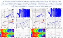
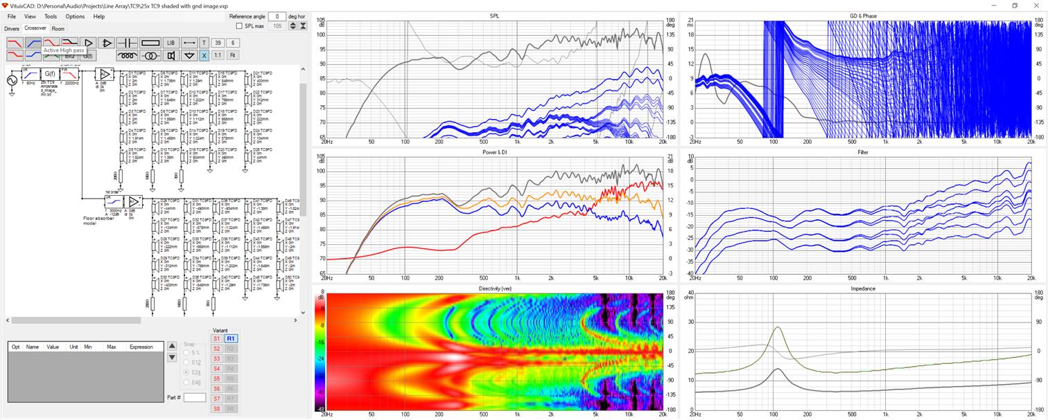
It was easy to create a frequency shaded array with ground image because my unshaded array with ground image simply had the shading filters shorted out.
Unshorting them I see something that appears to good to be true except for the polar map but there is an explanation for that. This array has a ground image and the mic is at the center of the primary image and well offcenter of the ground image array. Thus we get two beams, a real one and a virtual one that in reality is buried in the ground. Its not immediately obvious why that 2nd beam is at -45 degrees...If I set the mic offset to zero, we get a single beam.
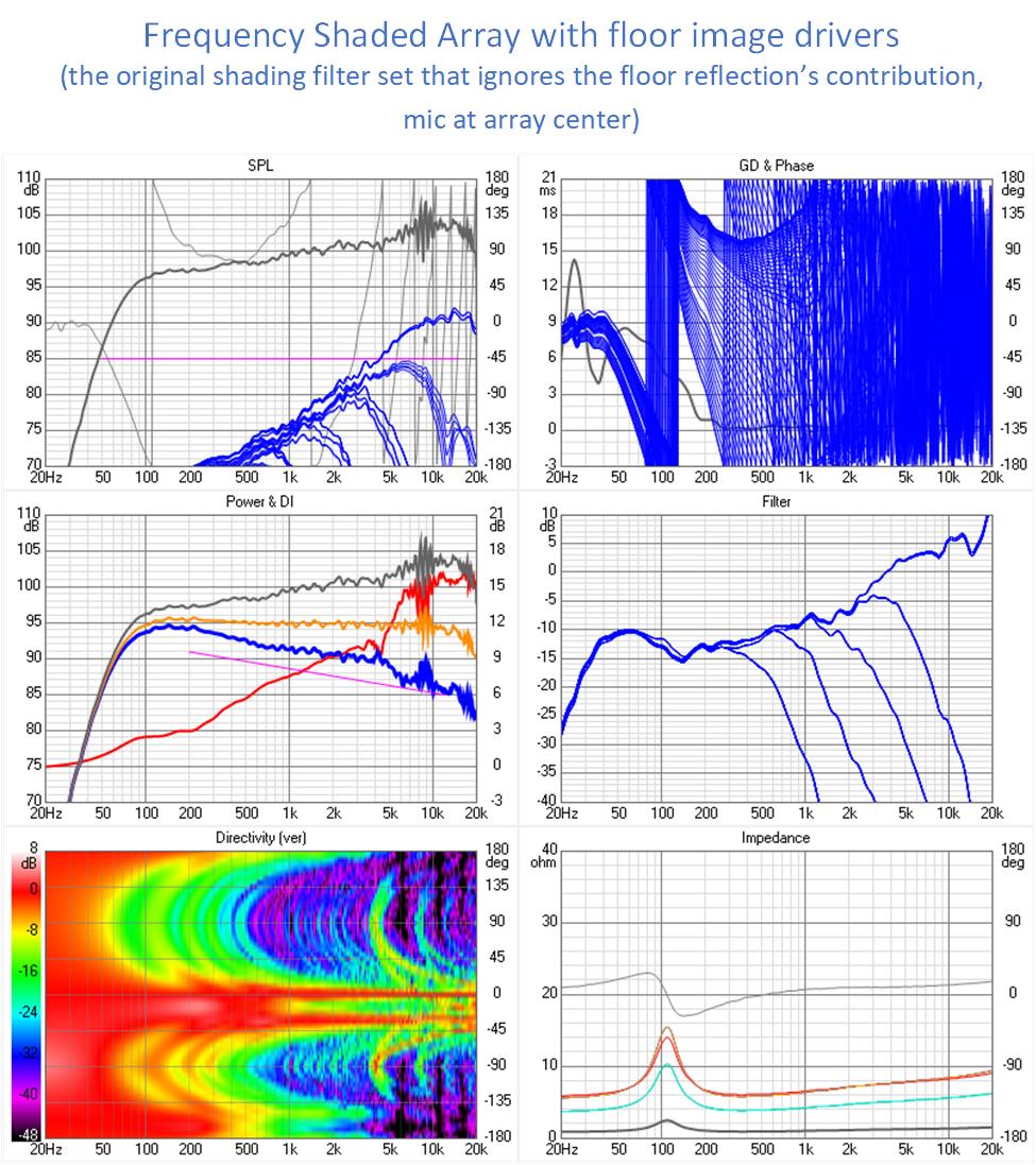
This array is equalized to the orange room response which is nicely flat. The only reflection artifact is the combing between 8 and 10 khz. It will be interesting to see if modeling absorpton on the floor makes that go away. This is encouraging so I will go ahead and tune the simulation to match Wesayso's listening position.
Unshorting them I see something that appears to good to be true except for the polar map but there is an explanation for that. This array has a ground image and the mic is at the center of the primary image and well offcenter of the ground image array. Thus we get two beams, a real one and a virtual one that in reality is buried in the ground. Its not immediately obvious why that 2nd beam is at -45 degrees...If I set the mic offset to zero, we get a single beam.
This array is equalized to the orange room response which is nicely flat. The only reflection artifact is the combing between 8 and 10 khz. It will be interesting to see if modeling absorpton on the floor makes that go away. This is encouraging so I will go ahead and tune the simulation to match Wesayso's listening position.
Attachments
Last edited:
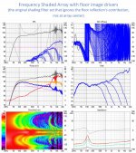
Now I have a model with ground image, first driver raised a bit above the floor to allow for cabinet bottom and feet and simulated and shaded for a mic height of 952mm, still at a listening distance of 4m.
Setting frequency shading corner frequencies to keep reflection relative phase shift below 90 or even 180 degrees turned out to be impossible - so I set them as i would for the same array without a floor reflection.
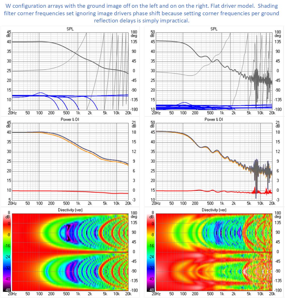
Comparing simulated equalization results we see the consequences of the imperfect shading are combing between 8-10 khz. Modeling the absorption of a carpet with a shelf filter that attenuates only the ground image above 3 khz by a max of 9 db, we find most of that combing is eliminated.
Setting frequency shading corner frequencies to keep reflection relative phase shift below 90 or even 180 degrees turned out to be impossible - so I set them as i would for the same array without a floor reflection.
Comparing simulated equalization results we see the consequences of the imperfect shading are combing between 8-10 khz. Modeling the absorption of a carpet with a shelf filter that attenuates only the ground image above 3 khz by a max of 9 db, we find most of that combing is eliminated.
Attachments
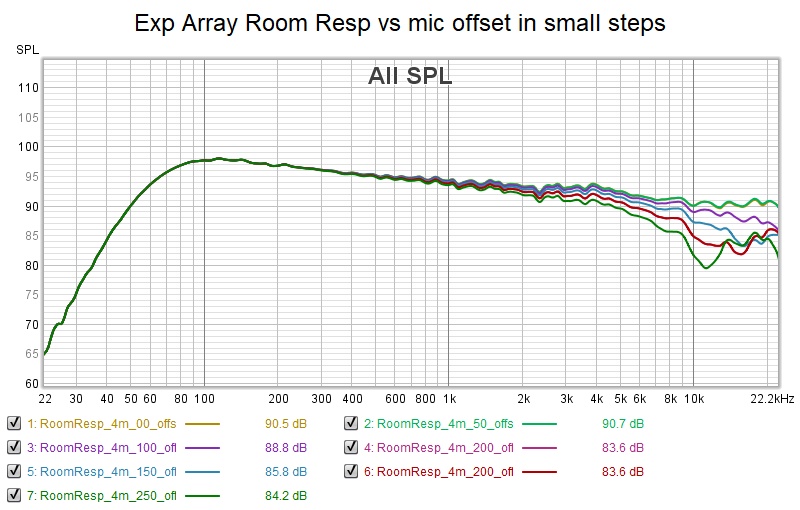
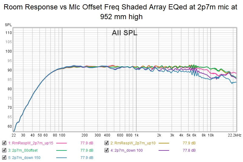
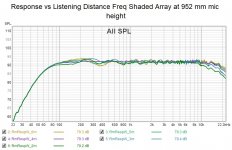
Here is the response vs microphone offset for the array with a listening distance of 2.7m. Its response also seems quite invariant with listening distance; there was only marginal improvement when I re-EQed for the shorter listening distance.
I noticed that Vituix is enforcing a +- 2m baffle height limit where this array configuration needs about 2.2m. The top 3 drivers were all given a Y value of 2m despite my best efforts. As these are only driven with low frequencies, I don't think it affects simulation accuracy at all. In fact, I disabled those drivers completely and all I lost was a little bass.
Attached is an update on the calculator showing how I grouped and shaded the drivers. First order IIR low pass filters didn't work nearly as well.
Attachments
Thanks for these simulations. The results do look promising for a certain fixed height listening spot. And it holds true for varying listening distances from there on.
It does scare me a bit how narrow angled that ideal spot looks though.
I've asked my girl if I should go for an improvement for seated listening at the cost of a possible change/tonal degradation at 'other' positions. Her answer was pretty clear: No! The whole concept seemed foreign to her. Why would anyone do that. I can feel that, as I did let go of some focus on the sweet spot to win in tonal balance over a wider area.
Did you try a shading pattern as used in Keele's CBT? Meaning getting the unshaded elements at floor level (with the ground plane making up the other half of it) and shade it from there on going up? Just out of curiosity it would be something I'd like to see. Keep the EQ level at a 'normal' listening height.
I don't expect it to do wonders, just trying to figure out if we can predict patterns by examining these data points.
Last edited:
Well the reason you might want to do it would be in a programmable fashion for when you were home alone. Maybe they would make a movie about it
The vertical narrowness also concerns me but I'm thinking about a system for when I'm at my desk where 95% of my listening would occur. But I would like to be able to walk around and I'd like it to sound good in the next room so today I was going to see if I could increase the number of full range driven drivers without degrading the response very much within the vertical sweetspot. The criterion I used to derive the frequency shading corners doesn't seem to matter so much and so I suspect I could get away with violating it to some extent. With the frequency weighting we get smoothly falling power response so that at least is good.
One of Keele's articles I think has simulations of a variety of array configurations and shadings. I wouldn't be surprised if the one you described is in that set. But won't that project the vertical beam along the floor? Legendre shading centered on ear height would be better but also not likely much different from the Dave Smith shadings I showed a few days ago.
As I recall those shaded arrays looked good vs distance except that the further out one went, the more the treble rose. If that rise in treble weren't there, they would have looked as good in that respect as the frequency shaded arrays. I would like to understand where that rise comes from. I should take another look at that with ground image drivers in place since that rise isn't in the frequency shaded array.
.
I thought it would be interesting to look at the image driver response at the LP separate from the dirrect response. I did this with the shelf filter that emulates a carpet or throw rug that provides up to 9 db of absorption in the treble both on and off. Combing levels in the treble are cut roughly in half with the filter in place. i don't see a reason for that peak in the image response at 7.5 Khz in any of the Vituix graphs.
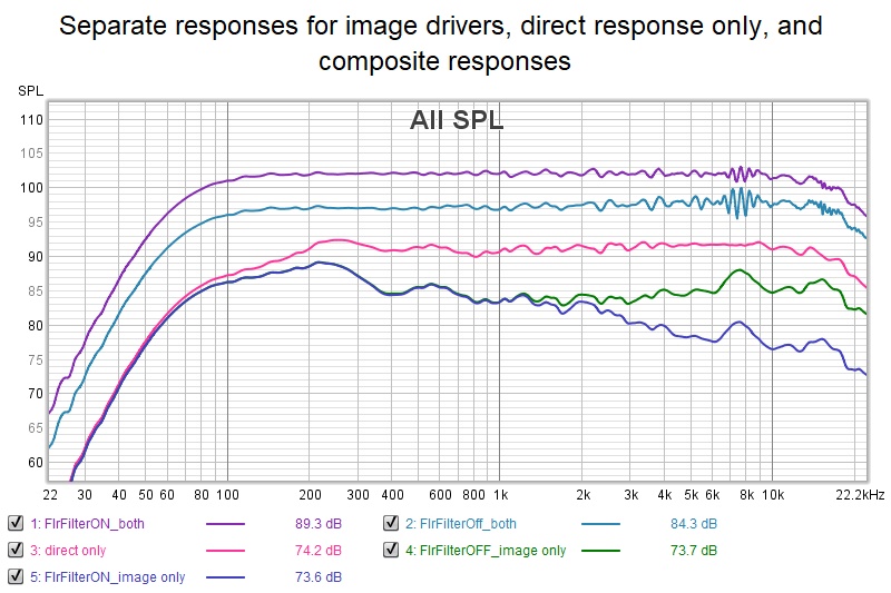
The top two traces on the graph were raised 5 and 10 db respectively for visual separation. The direct and image only traces are at their original levels, with the image about -7db relative to direct.
I did this graph hoping to see a reason why the long delayed image response doesn't "hurt" the composite response more than it does. The only thing I see is that the image drivers sum to a relatively flat response, except for that 3 db peak at 7.5 khz, coincident with the combing.
Attachments
Last edited:
Well, that's the thing, even though the CBT was shaded like that, the listening level was used to set the frequency curve, that made me wonder about it. Basically using that shading and the thing missing to make it a CBT would be the time delay from the bent shape.
The shading at floor level while EQ-ing at listening level does seem interesting to me.
Basically we would be EQ-ing off axis.
The shading at floor level while EQ-ing at listening level does seem interesting to me.
Basically we would be EQ-ing off axis.
I'll get to that for you but this should be interesting:
Here is the image array viewed at the LP. The room response curve looks reasonable but everything else looks pretty broken, doesn't it?
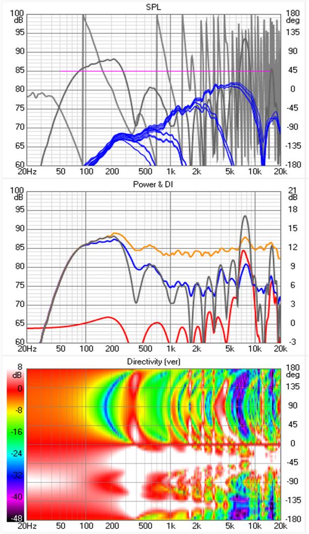
notice there is a vertical lob at 7.5 khz or so accounting for the image peak there.
Now view the image array from its design height, -952mm:
Sanity is restored! The polar maps in the first slide may be broken but the calculated room response can be trusted (as much as anything else in these sims). Its just that image array is viewed from what for it is a far off axis angle.
Here is the image array viewed at the LP. The room response curve looks reasonable but everything else looks pretty broken, doesn't it?
notice there is a vertical lob at 7.5 khz or so accounting for the image peak there.
Now view the image array from its design height, -952mm:
Sanity is restored! The polar maps in the first slide may be broken but the calculated room response can be trusted (as much as anything else in these sims). Its just that image array is viewed from what for it is a far off axis angle.
Attachments

Here is the at_floor shaded array simulation. Like all sims with ground image drivers, except perhaps CBT, it showed an unrealistically high degree of combing which I tamed by a negative gain high shelf filter that brings up to 9 db of attenuation starting at 3 khz. (just like in the immediately previous set of sims).
The room response is good except for the residual combing. Its not perfectly flat because I grabbed the screen image when mic was at 600 mm height while equalization occurred at 952 mm. That was because I had just captured the data for this graph of response vs mic ht.

As expected, giving highest weight to the drivers closest to the floor results in a rising equalization filter response. If you drop the outliers at 800 and 1200 mm, the rest of the responses are nicely flat but that vertical window isn't any wider than we had before. I think it would be better with the highest weight drivers in the center and with some frequency shading to reduce the combing.
You may notice that what I've implemented is a very crude approximation to Legendre shading. I played with resistor values enough to be confident I didn't leave any smoothness on the floor. I've notice before that weights aren't very critical although there is a theoretical directivity benefit for precise Legendre coefficients on a CBT.
The room response is good except for the residual combing. Its not perfectly flat because I grabbed the screen image when mic was at 600 mm height while equalization occurred at 952 mm. That was because I had just captured the data for this graph of response vs mic ht.
As expected, giving highest weight to the drivers closest to the floor results in a rising equalization filter response. If you drop the outliers at 800 and 1200 mm, the rest of the responses are nicely flat but that vertical window isn't any wider than we had before. I think it would be better with the highest weight drivers in the center and with some frequency shading to reduce the combing.
You may notice that what I've implemented is a very crude approximation to Legendre shading. I played with resistor values enough to be confident I didn't leave any smoothness on the floor. I've notice before that weights aren't very critical although there is a theoretical directivity benefit for precise Legendre coefficients on a CBT.
Attachments

Yes, that doesn't look promising at all. I was glancing at the post above it, with the peak at 7K.
There are so many ways to shade the arrays, looking at what the mirror image does might be a good way to find out how to best implement it.
I'd look at array only (not trying to shade with the floor mirror in mind) and try to implement shading with simple first order filters based on driver distances to listening position (mic).
I would not mind a little wiggle at the listening position, but reduction in the side bands seems worth it to try and accomplish.
Looking at the mirror with mic underground was a good sanity check and gives confidence in its contribution to the above ground sound field. When I first started doing this, I observed the array from a progression of very high angles down to the actual listening position to see the progression from full on combing to destructive combining produced response ripple. That also built confidence. But still there is the gap of what is lost by not having ceiling reflections (mitigated by assuming ceiling absorption for the HF) or 2nd and higher order reflections. My feeling is that these missing elements would tend to fill in the combing holes, so to speak, making things a little better than they look without them.
Yes. Shade based on primary image since the virtual sources are so far away and ~7db down relative to the physical drivers and because shading based on image drivers isn't productive
Passive filters are a pesky implementation detail but with a big cost savings. I can see 5 groups of 5 drivers, each group a string of five in series with one end grounded, tops connected with inductors. The lower in frequency, the steeper the slope.
The amp load impedance shouldn't be too bad; like a single driver at LF, higher at HF...
Now to actually try to do it...
Last edited:
- Home
- Loudspeakers
- Full Range
- Full range line array for wall or corner placement