
One more tweak evening out the top half octave.
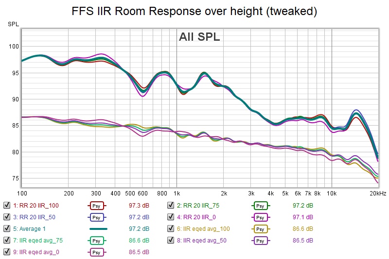
I have to ask myself if I could do as well with the sharper lin phase filters. I think so. The improvement here is in the top half octave and amplitude weighting of the 5 central drivers and that would carry over. Treble does fall off after 15 khz but does so consistently over the window and so can be brought up.
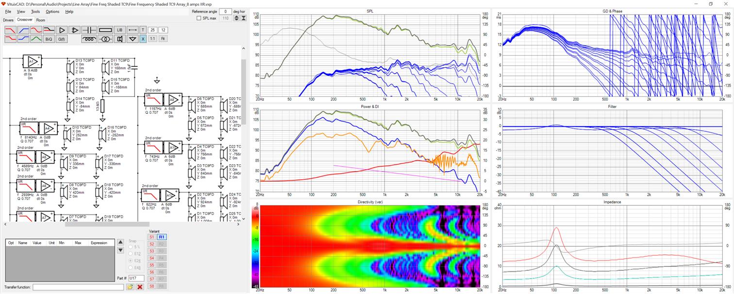
Here is a screenshot showing my shading on the central 5 drivers, the 2nd order IIR LPFs, the unequalized room response in orange and the vertical directivity, among other things.
The difference in LinPhase vs IIR is the upper mid bass dips in the room response that are filled via equalization; probably not deep enough to limit dynamics but something to be aware of.
With amp requirements down to 8 and an IIR solution outlined, the MiniDSP 4x10 becomes a candidate for implementation. If going that way, I would still do a global FIR EQ via JRiver.
I have to ask myself if I could do as well with the sharper lin phase filters. I think so. The improvement here is in the top half octave and amplitude weighting of the 5 central drivers and that would carry over. Treble does fall off after 15 khz but does so consistently over the window and so can be brought up.
Here is a screenshot showing my shading on the central 5 drivers, the 2nd order IIR LPFs, the unequalized room response in orange and the vertical directivity, among other things.
The difference in LinPhase vs IIR is the upper mid bass dips in the room response that are filled via equalization; probably not deep enough to limit dynamics but something to be aware of.
With amp requirements down to 8 and an IIR solution outlined, the MiniDSP 4x10 becomes a candidate for implementation. If going that way, I would still do a global FIR EQ via JRiver.
Attachments


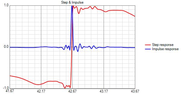
Found that the room response exports don't have any phase attached so I exported the axial response and went through Rephase and REW to get a phase correction, with this as the final impulse and step response
Attachments

I turned my attention back to my own SB65 arrays this morning and I think its time to declare victory. My latest configuration requires only 5 amplifier and DSP channels per side, which I can do with hardware I already own and its response is within +/- 1 db over the +/- 100 mm vertical window centered on my seated ear height and what variation there is at the high end is effectively just a slight change in voicing.
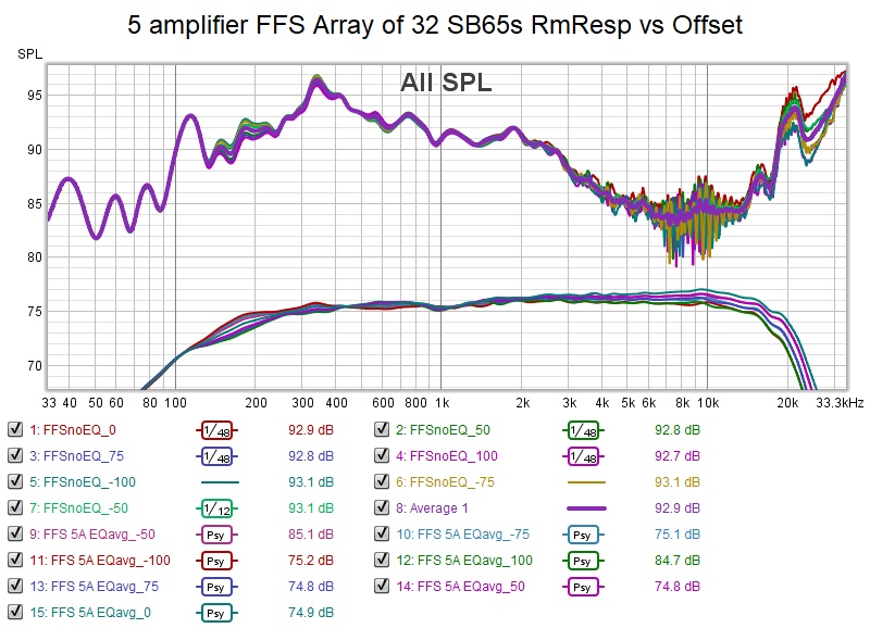
The upper group is the unsmoothed unequalized responses which were averaged and then equalized to produce the lower group of traces. I don't have a room curve filter in place but if I did the slight rise in the treble would be come a slight variation with height of the falling slope of the treble.
Here is a screenshot showing my amplifier configuration and filters. I've done this with linear phase filters because they work better than IIR and don't cost any extra when implemented in Jriver. Based on previous work, I'm sure IIR with 2nd order filters would work but with more variation.
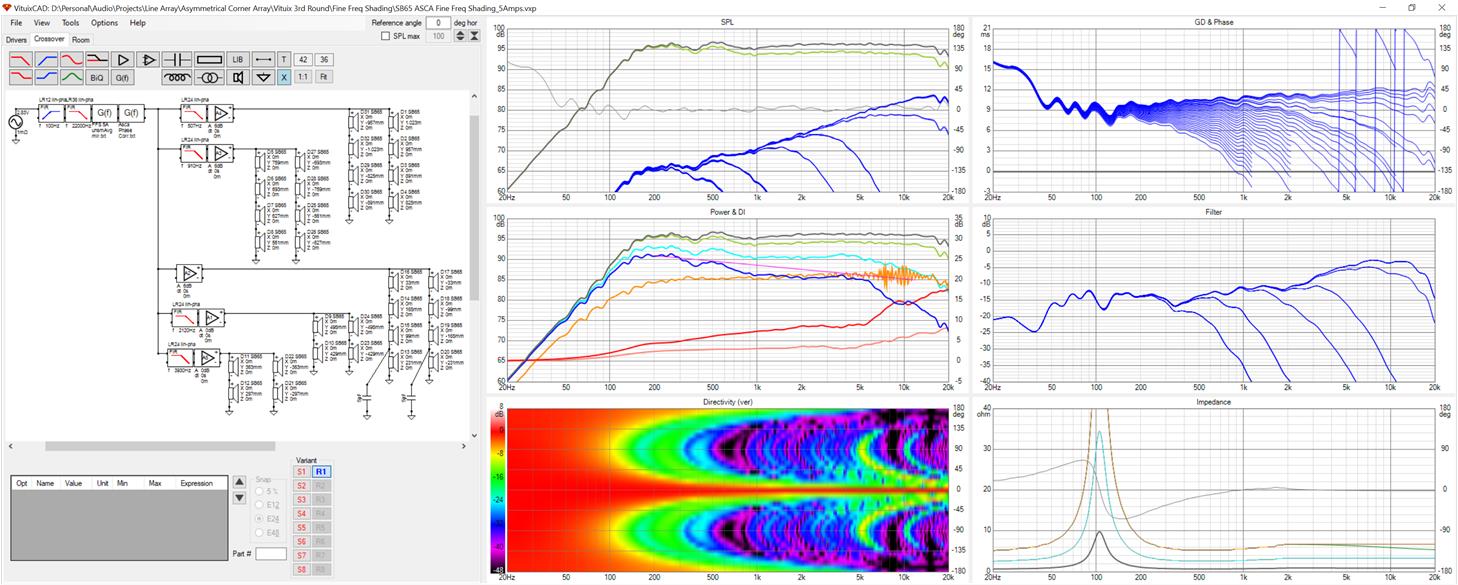
Notice the two capacitors in the lower right corner of the schematic. These roll off the outer two drivers of the central 8 driver group with a corner near 10 khz for an incremental improvement in the top octave, saving an amp and DSP channel.
While the response is very good around my seated ear height its actually quite bad at standing ear height - about -560 mm offset
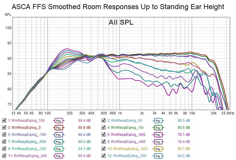
This is to be expected given the small number of drivers that are driven full range. The large drop with increased offset between 500 Hz and 1 khz is related to the low pass filter cutoff frequencys and vertical offsets at which they cut in. From the ends of the array working in, the filter cutoff frequencies are 507, 910, 2120 and 3930 Hz.
The upper group is the unsmoothed unequalized responses which were averaged and then equalized to produce the lower group of traces. I don't have a room curve filter in place but if I did the slight rise in the treble would be come a slight variation with height of the falling slope of the treble.
Here is a screenshot showing my amplifier configuration and filters. I've done this with linear phase filters because they work better than IIR and don't cost any extra when implemented in Jriver. Based on previous work, I'm sure IIR with 2nd order filters would work but with more variation.
Notice the two capacitors in the lower right corner of the schematic. These roll off the outer two drivers of the central 8 driver group with a corner near 10 khz for an incremental improvement in the top octave, saving an amp and DSP channel.
While the response is very good around my seated ear height its actually quite bad at standing ear height - about -560 mm offset
This is to be expected given the small number of drivers that are driven full range. The large drop with increased offset between 500 Hz and 1 khz is related to the low pass filter cutoff frequencys and vertical offsets at which they cut in. From the ends of the array working in, the filter cutoff frequencies are 507, 910, 2120 and 3930 Hz.
Attachments


Was I really done? Of course not. Concern was expressed about the laser beam focus and that change in slopes with height might be perceptible. What was really needed was a gentler touch like Wesayso has in his passive shelf shading. I tried several things but what worked amazing well was reducing my filter slopes to 2nd order and the doubling the corner frequencies for the 3 groups of drivers closest to center.
Response within the original +/- 100 mm target window is within +/-.6 db!
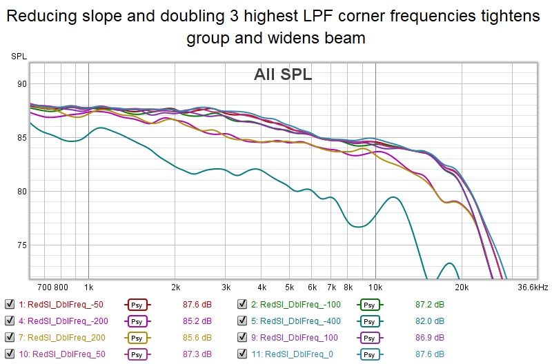
I didn't re-eq to get this plot. I was in too much of a hurry to see how tight the group was - and that is what you should look for in the picture. The tight group at the top is the original +/- 100 mm window. The next two traces below are + and - 200mm. The outlier is -400mm; I didn't make it to standing height but I did achieve a tighter cluster near nominal ear height and slower degradation with movement away from it.
Response within the original +/- 100 mm target window is within +/-.6 db!
I didn't re-eq to get this plot. I was in too much of a hurry to see how tight the group was - and that is what you should look for in the picture. The tight group at the top is the original +/- 100 mm window. The next two traces below are + and - 200mm. The outlier is -400mm; I didn't make it to standing height but I did achieve a tighter cluster near nominal ear height and slower degradation with movement away from it.
Attachments


Excellent! Though we can't promis anything about how it will sound until we try 🙂.
There's good bundling and focus within the entire (plus/minus 10cm) vertical area now, this 'should' work, right?
There's good bundling and focus within the entire (plus/minus 10cm) vertical area now, this 'should' work, right?
Here is a Vituix screenshot showing my wiring diagram and filter configuration. I see I misspoke earlier - all the filters are 2nd order. Corner frequencies for the 2 highest frequency filters were doubled from the calculated 90 degree phase shift frequencies.
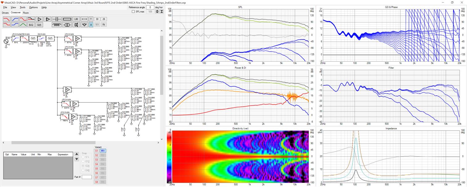
There are 8 drivers in array center driven full range. Flanking them are two groups of 4 drivers and further out, two groups of 8 drivers. Furthest out drivers have the lowest filter corner frequencies now at 507, 910, 4240 and 7860 Hz.
There are 8 drivers in array center driven full range. Flanking them are two groups of 4 drivers and further out, two groups of 8 drivers. Furthest out drivers have the lowest filter corner frequencies now at 507, 910, 4240 and 7860 Hz.
Attachments

Excellent! Though we can't promis anything about how it will sound until we try 🙂.
There's good bundling and focus within the entire (plus/minus 10cm) vertical area now, this 'should' work, right?
I used to get beat up for telling my manager I thought something "should" work. He wanted me to state definitively that it would work!
If anything is worth trying, this certainly is!
Does anyone have connector suggestions? I have to bring up 5 pairs. Speakons only go up to 4 pairs. I could use a 2 wire speakon for the center group and a 4 pair Speakon for the flankers but a single connector would be nice. Or a 10 terminal barrier strip with a solder tail that would stick through the cabinet wall.
Horizontal didn't change, right? This should provide a good base, the rest of the room will have its influence on the lower sections, but nothing you couldn't handle with some room EQ.
Too bad i'm focussed on keeping a good standing performance, though I doubt it will look equally pretty with minimum phase filters. That might still work though, if someone would be willing to try a few sims to see what can be done.
Here the smaller size drivers in the array do help to get results like these. Not a bad choice at all. As long as there's something on the bottom with enough grunt and dynamics to support the lower end. Big subs, right?
Is your directivity graph normalised?
Yes I have subs. Too many for my new small room but just a single pair of 15's with 14 mm Xmax should do nicely. Room will definitely influence.
Last week I did a version with 2nd order IIR filters. Results were not quite as good and there were bigger dips in the midbass to be equalized but still very good.
Here is directivity.
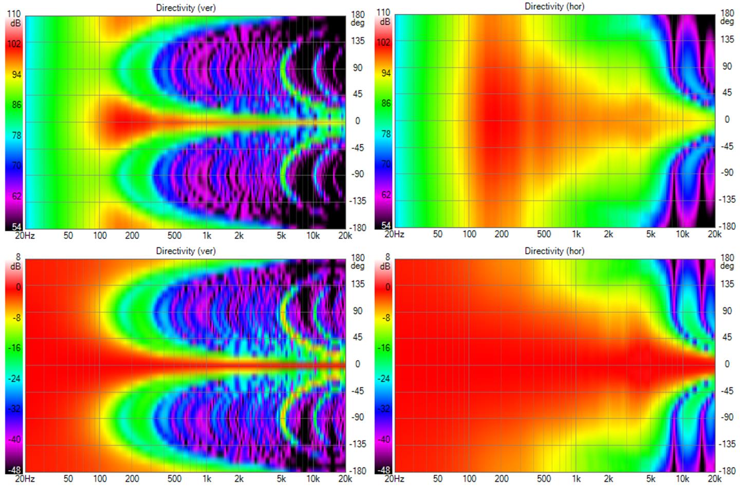
the fading away of the main beam un-normalized is just the room curve filter attenuation.
Last week I did a version with 2nd order IIR filters. Results were not quite as good and there were bigger dips in the midbass to be equalized but still very good.
Here is directivity.
the fading away of the main beam un-normalized is just the room curve filter attenuation.
Attachments

Looks awesome, (like a needle pin) can't wait till you get the chance to try it.
My own passive solutions will have to wait a while, but as all sims I've done... moving further away, up or down (within limits) and even sideways at longer distance (standing heights) looks promising and better than the unshaded in every regard, I'd say it's a go. Who knows, I may find some more refinements.
My own passive solutions will have to wait a while, but as all sims I've done... moving further away, up or down (within limits) and even sideways at longer distance (standing heights) looks promising and better than the unshaded in every regard, I'd say it's a go. Who knows, I may find some more refinements.
Well I started this for something to do during shutdown. I'm not sure when I will be able to start working on it.
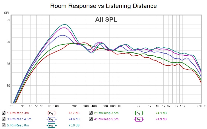
In the meantime, I checked response vs listening distance. The extravagant 11 amp+DSP channel solution was listening distance independent in that the slope of the roll off doesn't change, just the point at which it starts down.
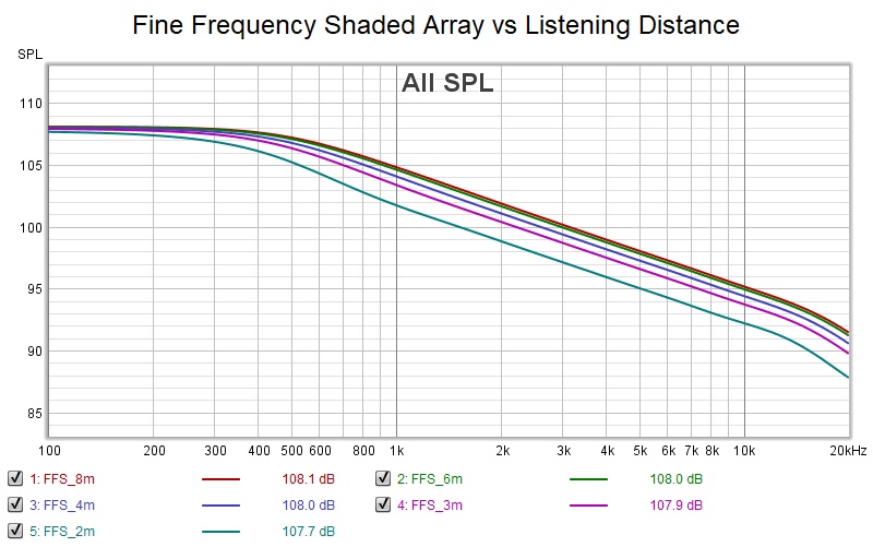
(the graph is for 24 points at/near TC9 spacing with a lin phase 4th order LPF on each successive driver pair flanking center)
The practical 5 amp solution has a rolloff slope change with distance that makes a 3m equalization pretty bad at 6m
I may want to invest in a few more amp channels to be able to do better than this in case I every want to play in a larger room or at least rewire in such a way to preserve the option with patchcord like changes.
In the meantime, I checked response vs listening distance. The extravagant 11 amp+DSP channel solution was listening distance independent in that the slope of the roll off doesn't change, just the point at which it starts down.
(the graph is for 24 points at/near TC9 spacing with a lin phase 4th order LPF on each successive driver pair flanking center)
The practical 5 amp solution has a rolloff slope change with distance that makes a 3m equalization pretty bad at 6m
I may want to invest in a few more amp channels to be able to do better than this in case I every want to play in a larger room or at least rewire in such a way to preserve the option with patchcord like changes.
Attachments


Could you test the one before you made your last tweaks? The one that you showed in post: #644?
As I just looked at the Ath4 thread and figured the top end on most (good) horns would show a similar result with varying height as your graphs. Except yours does less to light up the floor and ceiling.
As I just looked at the Ath4 thread and figured the top end on most (good) horns would show a similar result with varying height as your graphs. Except yours does less to light up the floor and ceiling.
Here it is (the version with 5 amps, linphase 4th order filters) both with and without wall reflections. It is somewhat better.
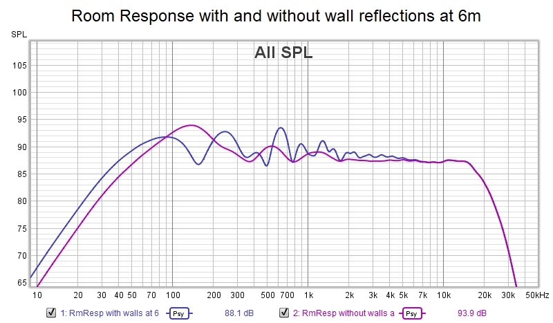
Down around and below 200 Hz, the room is going to have its way with the shading algorithm...
Down around and below 200 Hz, the room is going to have its way with the shading algorithm...
Attachments

As to horns. Typically, they lose vertical pattern control early enough to suffer floor and ceiling bounce nulls because most horns simply aren't tall enough to do otherwise. But within the pattern, they can be designed to have constant directivity...quite constant in recent ATH4 postings. I looked at his before and didn't like what I saw. In retrospect perhaps best way to marry waveguide to expanding line is brickwall filter; should work well if horizontal pattern match
Last edited:
I started simulating in VituixCAD as well. How do you configure the driver diameter in the crossover tab? Thanks in advance!
Driver diameter determines directivity which Vituix needs. If you have measurements - a polar set thereof - you put them in a directory and point to them on the driver tab (upper left corner region), not the XO tab.
If you don't have polar measurements but you have an axial measurement, you use the diffraction tool to synthesize the polar set and then point to the directory containing them on the driver tab. First you browse to the directory, go inside it, group select the files and press return. For all this work, the angle of the (synthesized measurement) has to be in the file name, default is "...._xx" .
If you don't even have an axial measurement, you can use the SPL trace tool to trace data sheet FR and Z graphs, then take the traced FR to the diffraction tool.
In the diffraction tool, enter the driver diameter, count of 1 and baffle dimensions in the lower center region. Off on the lower left, browse to the direction containing your starting FR.txt file, which is where the synthesized directivity files will end up, and select that starting axial measurement_00.txt. Then check the boxes for directivity, vertical plane, and negative angles and enter "5" in the step size and a listening distance. Don't check the boxes for reflections. I think if you check feed speaker it will auto enter the file name etc into the driver tab for you but I usually do that myself.
- Home
- Loudspeakers
- Full Range
- Full range line array for wall or corner placement