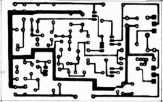
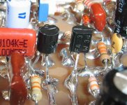
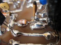
Here is the copper image...well...i do not know how to use
This method...as i have developed my own since the sixties...i hope you can understand watching the image.
I will ask John Mateus to make something more clear to me.
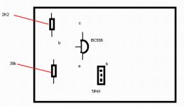
Here is another image.
regards,
Carlos
This method...as i have developed my own since the sixties...i hope you can understand watching the image.
I will ask John Mateus to make something more clear to me.
Here is another image.
regards,
Carlos
Attachments

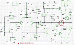
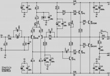
Here is Mr. Greg Erskine schematic...a very gentle offer
Very good schematic Greg had produced.
The input sensitivity can be reduced avoiding the voltage attenuator you have in the input
R10 and R11 can be tweaked to reduce the circuit gain
Also the big input electrolitic condenser can be reduced, it was there because this circuit was connected with a very low impedance....also the input voltage attenuator had low impedance too.
Thanks Greg.
regards,
Carlos
Attachments
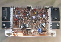
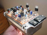
In one hour, my fast stereo version will be playing good sound
My satisfaction is guaranteed...ahahahha...as i have already listened, no surprises will come..for sure.
It is almost ready...some connections to output transistor... a double check. a cleaning procedure between those checks... some adjustments and ....Happyness!
Yes...there are modification in the input attenuator (that will be removed near future)...to match my own needs.
The rigth channel had a lot of things removed...i will evaluate a more clean amplifier, without any bypasses and other details...how will sound clean, dirty and nude compared with the standard diagram already tested.
I am always trying comparisons....nothing is rigth to me..no last words related amplifiers..only the A to B comparison can tell me something....all the rest, is delirium in my point of view...or.... ear/brain adjustment.
Two amplifiers...face to face....in a fair dueling session will be tbe must.
I hope you find courage to try.
regards,
Carlos
Attachments
A friend asked me to suggest modifications...what a hell boys!
I am not the forum owner!...the forum is public.....opened to everybody to read and suggest and tell whatever they want.
I am not a designer...i have only 46 years of practice.... around 3.5 K amplifiers constructed...several of them exploded in my face...others i made supply invertion and sent em to hell.
But i turn tired to construct others designs...and decide to join some ideas i had...a very simple tophologie and to make my own...and it is running and sounding very good i have to say.
But there are a lot of errors there...of course...the gain is too much high....i was lazy to change feedback resistor, as all the adjustments made will have the need to be repeated...i prefered just to put a resistor attenuator and ready to go.
I am not an industry...this is not a professional amplifier...this is a diy hobby home made thing to make us happy...to enjoy...to make error and to fix them..to evolute and learn things...included that i need to study more.
I made calculations...the ones i know...but for sure there are errors there.
If you want to fix some....produce your variations, put your name..publish here, or open your own thread and let's go ahead folks...let's dance the life dance...this is our hobby...have fun with me.
Everybody can modify.....suggest modifications....well...i have made mine and i can guarantee that work and work very well...the ones that suggest things may have to construct too to give a guarantee to the people.
Alike a frankstein....Doctor frankstein creature....he used a head from A.... arms from B......legs form C....that's what i did.... the idea is Frankstein idea.... and as my choice was the bootstrapped..used by Hugh Dean for years long....i decided not to use anyone of his secrets...and to make something good avoiding to use his top hi end ideas (his ideas works fine..for sure!)....and i have made mine with ohms law and a small calculator.....finally...after so long years...my adventure started.... a toy amplifier made...and God blessed me with a fully working amplifier..stable and sounding GREAT!
Problems that modifications will create is that i have used low speed transistors....they cannot oscilate at very high frequencies...also they have not that gain...so.... update or upgrade may have problems starting oscilations that i do not have... i am not picking any Radio frequency...and my finger goes into the input and only the 60 hertz that i captured from the mains voltage magnetic field...no strange noises...no broadcasting radio...nothing there..only 60 hertz...ahahahah..undistorted!
But you can cooperate....including modifications.... creating diagrams...posting here or everywhere...i will be happy and glad to have cooperation and company...people around making noise here... posting things and discussing practical things...as i am a DIYer.... im not a designer.....The sexual intentions of the long tail do not mind to me.
But please..support your ideas with real circuits ...real working things....those things we extract from simulator (i have one too) sometimes do not works exactly the way we had imagined in real life.... things real please guys.....real amplifiers please.
regards,
Carlos
Negative...i am not so bad...images has less than 70K in average.
Bandwidth economy...more images using less data.
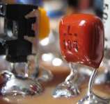
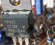
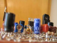
Image show that drivers do not need heatsink.... the choice of current was made thinking to avoid those heatsinks.
No heatsink needed represents less insulators, screws and all stuff..also you can choice smaller transistors, and those smaller ones can be selected to show better gain and lower noise....in special when thinking to the VAS.
regards,
Carlos
Bandwidth economy...more images using less data.
Image show that drivers do not need heatsink.... the choice of current was made thinking to avoid those heatsinks.
No heatsink needed represents less insulators, screws and all stuff..also you can choice smaller transistors, and those smaller ones can be selected to show better gain and lower noise....in special when thinking to the VAS.
regards,
Carlos
Attachments
- Status
- This old topic is closed. If you want to reopen this topic, contact a moderator using the "Report Post" button.
- Home
- Amplifiers
- Solid State
- Full throttle construction of amplifiers