I basically followed the Test Circuit 2 schematic in the CineMag CMLI-15/15B datasheet:
http://cinemag.biz/line_input/PDF/CMLI-15-15B.pdf
RED/4 - RCA connector (+)
BRN/1 - RCA connector (GND)
YEL/8 - C2 thru-hole connected to Pin 4, TPA3116 (RINP)
ORG/5 - C3 thru-hole connected to Pin 5, TP3116 (RINN)
BLK/6 - J1 thru-hole connected to ground
WHT/7 - not connected, but will connect to Earth when I put the amp in an enclosure
I based my decision on buying the CineMag CMLI-15/15B transformers using my ARC LS7 line stage with an output impedance of 200ohm and the TPA3116's gain set to 26dB (30kohm input impedance). I also considered Jensen JT-11P input transformers. Matt Garman from this forum lent me his Edcor TTPC-15K/15K input transformers. These sounded pretty good with the Sure TPA3116 BTL amp, but I prefer the results I got with the CineMags.
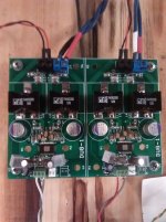
It's been almost a week since I've built this amp and I've been playing many LP's, SACD's and CD's. I have to say this is the best TPA311x amp I've heard in my system so far. It clearly is a refinement over my modified Yuan Jing TPA3116 blue amp. The fine detail and tonality really puts this amp into another level compared to the Class D amps I've been playing with the last year. What is really impressive is the bass definition and driver control this amp has over my Klipsch Forte II 12" woofers. It's very tight.
I am driving this with a tube line stage and tube phono stage and the tube bloom comes through clearly. It really is impressive and casts a huge three dimensional soundstage. The separation between performers really allows me to hear the interplay between musicians. This is clearly evident on large orchestral music and rock music with loud, complex passages. The soundstage doesn't collapse into a shouty mess.
The Copper heat sinks and CoilCraft inductors stay cool. I almost could ditch the heat sinks, but they add a bit to the visual appeal of DUG's amps. I have my amp set up with 26dB gain.
How much would it cost to build your setup?
It's been almost a week since I've built this amp and I've been playing many LP's, SACD's and CD's. I have to say this is the best TPA311x amp I've heard in my system so far. It clearly is a refinement over my modified Yuan Jing TPA3116 blue amp. The fine detail and tonality really puts this amp into another level compared to the Class D amps I've been playing with the last year. What is really impressive is the bass definition and driver control this amp has over my Klipsch Forte II 12" woofers. It's very tight.
I am driving this with a tube line stage and tube phono stage and the tube bloom comes through clearly. It really is impressive and casts a huge three dimensional soundstage. The separation between performers really allows me to hear the interplay between musicians. This is clearly evident on large orchestral music and rock music with loud, complex passages. The soundstage doesn't collapse into a shouty mess.
The Copper heat sinks and CoilCraft inductors stay cool. I almost could ditch the heat sinks, but they add a bit to the visual appeal of DUG's amps. I have my amp set up with 26dB gain.
I believe DUG sells the BOM parts as a kit. I departed from the BOM using the following:
I do not claim that these are the best parts for this amp for everyone, but it works in my system.
- C6, C7: Panasonic SEPF OSCON 330uF/25V DC decoupling caps
- L1, L2: CoilCraft SER2918H-223L 22uH output inductors
- C19, C20: Rubycon ST PML 0.68uF/25V output caps
- C2,C3: CineMag CMLI-15/15B input transformers instead of input caps
- Heatsinks: RadioShack Copper PC Heatsinks, 0.5" x 0.5" (previously used these on Tripath Class D amp ICs with good results)
I do not claim that these are the best parts for this amp for everyone, but it works in my system.
Last edited:
Advice on capacitors
Looks like I missed out on ordering 0.68uf SMD capacitors for C19, C20.
Have 0.68uf small size film caps though (Wima, through hole)... also seen pics where DIYers have soldered a few through hole components on to SMD boards (with the help of a bit of extra solder?).
Worth trying? Anything I should be careful about?
Last edited:
I recommend that you try the ceramic caps in the BOM before trying to fit Wima film caps onto SMD soldering pads. There's just not much space to work with between the inductors and terminal blocks. On top of that, you'll have a significant amount of capacitor leads that can create interference issues.
I also have 0.1 uf SMD caps - what sort of effect will 0.1uf have vs 0.68uf in this particular circuit?
That is part of the LC output filter (L = inductor, C = capacitor). The LC values work together, along with your speaker's impedance, to remove high-frequency noise from the audio signal. The noise is a by-product of the way the class D amp works. However, the noise is far above what anyone can hear. The concern is really with EMI/EMF pollution between the amp and your speakers.
So, technically, you don't need the output filter at all. The datasheet for the tpa3116 talks about simply using ferrite beads around the speaker output to cut out most EMI/EMF, if your speaker cables are sufficiently short. Without any kind of filtering, you could possibly interfere with radio reception in your home, or possibly your neighbor's if you live in a multi-unit.
It's also possible to make the filter such that the cutoff frequency dips into the audible range, so worst-case you could filter out some high-frequency information in your music.
There are RLC filter calculators on the net, such as this one. Scroll down to the 2nd-to-last section, "Calculate the transfer function for RLC low-pass filter with R, L and C values" (not that circuit has the C in parallel with R, where R is your speaker). Using a .1uF cap raises the cutoff frequency into the 100kHz range, which I assume would still pollute some EMI.
Maybe a better place to start is this article, "Understanding output filters for Class-D amplifiers".
If you have a lot of those .1uF SMD caps, I think you might be able to stack them 7-high to get close to the 0.68uF value. Capacitors in parallel are additive, if I'm not mistaken.
If you can make them mechanically fit, and you can keep reasonable lead lengths (say, <5mm) then I'd say put on the film caps. Electrically their capacitance value doesn't change by any significant amount with applied voltage, but the capacitance value of a X5R/X7R ceramic can drop significantly.I recommend that you try the ceramic caps in the BOM before trying to fit Wima film caps onto SMD soldering pads. There's just not much space to work with between the inductors and terminal blocks. On top of that, you'll have a significant amount of capacitor leads that can create interference issues.
I'd put down a 1000pF or similar low value (but more importantly, low ESL) ceramic capacitor on the output capacitor footprint, then solder the leads of the film cap to the sides of this cap. In theory this makes your 680nF cap a 681nF cap, but the impedance at HF will be much better.
DUG,
I just received my boards today.
Thanks,
Bernard
Thank you for letting me know...some people don't.
Here is a picture of my amp in its current “work in progress” state. I have posted it to show that it is quite possible in fact to solder in the 250V 0.22uF bootstrap capacitors that I mentioned in post # 65.
I have not finished fiddling but I am enjoying the sound of the amp. Thank you DUG.
I did have a few of questions.
- I will be trying a master/slave stereo (2-channel) setup. Does anyone out there have any experience with this configuration?
- I would like to change the switching frequency to 500 kHz or 600 kHz. Any opinions on how to best go about it with this board?
- I will be using a Pass diy B1 buffer (unbalanced) for volume control. The TI 3116 data sheet states the following:
“In a single-ended input application, the unused input should be ac grounded at the audio source instead of at the device input for best noise performance. For good transient performance, the impedance seen at each of the two differential inputs should be the same.”
My B1 is configured with a 10 uF output cap per channel. My understanding of the TI data sheet suggests that I should connect the B1 output ground to the chassis via a 10 uF capacitor equivalent to the output cap that I am using on the B1. The B1 ouputs would then be connected to the amp where the unused input is jumpered to ground. What do you think?
Thanks.
Attachments
...
- I would like to change the switching frequency to 500 kHz or 600 kHz. Any opinions on how to best go about it with this board?
...
The best way would have been to cut the traces from ground of pins 13, 14, 15 before the IC was installed.
You can try to lift the pins from gnd without breaking them...very, very risky.
If you can wait to try the different frequencies then keep an eye on the gmarsh GB...he has commented on the possibility of another build.
http://www.diyaudio.com/forums/group-buys/269855-wiener-tpa3118-amplifier-card-42.html#post4297708
- Status
- This old topic is closed. If you want to reopen this topic, contact a moderator using the "Report Post" button.
- Home
- Group Buys
- GB for TPA3116/8 PBTL bare pcb