That's simply not the case. The critical bands vary in width across the frequency spectrum going from about 1/3 octave at LFs to about 1/20th octave nearing 10 kHz. Look up critical bands according to Zwicker and Moore. Moore's are much narrower than Zwicker's, but are based on more recent and probably more accurate data. In my software I use exactly Moore's ERB (Equivalent Rectangular Bandwidth.), so the smoothing varies with frequency. My software also has the option of using fixed (1/3, 1/6, 1/12, 1/24), Zwicker, Moore or none.
Fascinating!
So the audibility of a peak or dip depends on frequency.
That's simply not the case. The critical bands vary in width across the frequency spectrum going from about 1/3 octave at LFs to about 1/20th octave nearing 10 kHz. Look up critical bands according to Zwicker and Moore. Moore's are much narrower than Zwicker's, but are based on more recent and probably more accurate data. In my software I use exactly Moore's ERB (Equivalent Rectangular Bandwidth.), so the smoothing varies with frequency. My software also has the option of using fixed (1/3, 1/6, 1/12, 1/24), Zwicker, Moore or none.
While critical bands vary in width, the difference between Zwicker (critical bands) and Moore (ERB) is not as narrow as you state:
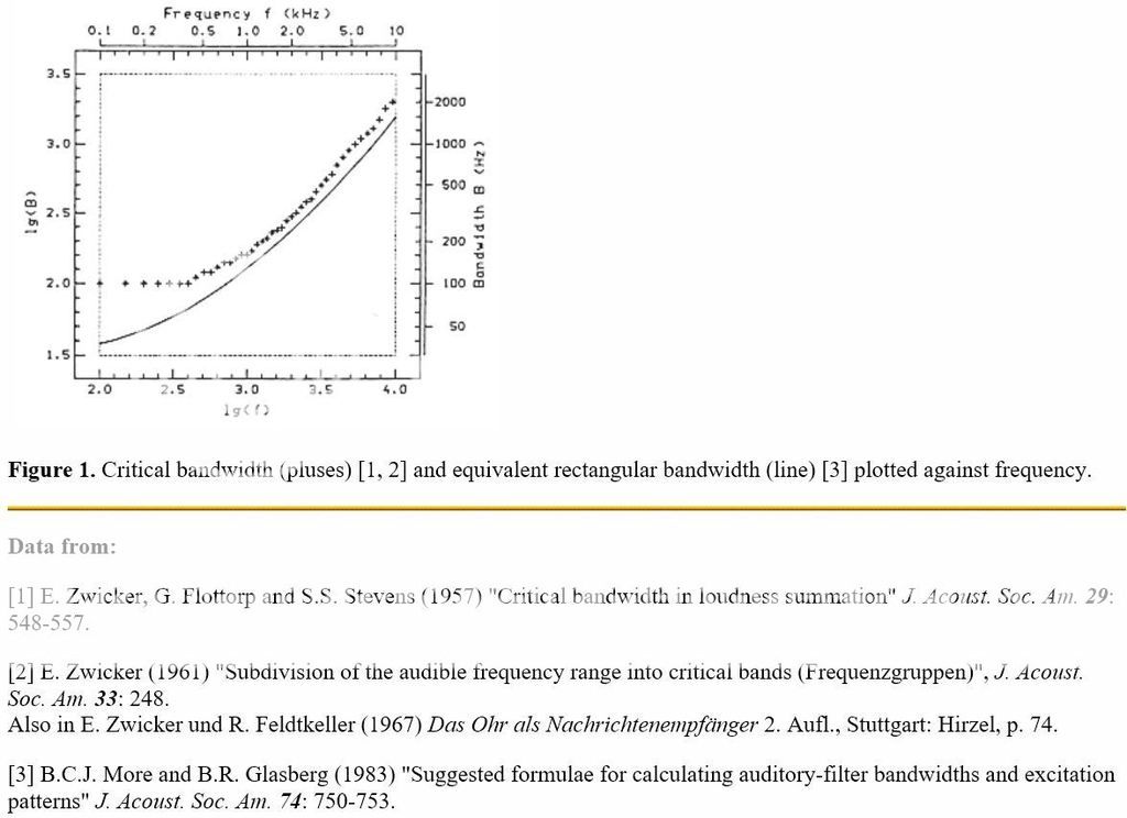
Auditory scales of frequency representation
ERB after Moore is very close to 1/6th octave above 5 kHz:
f BW (octaves)
50 1/1.17
100 1/1.97
200 1/3.01
500 1/4.42
1000 1/5.24
5000 1/6.15
10000 1/6.29
20000 1/6.36
As stated in post 7375: Displaying at higher resolution's than 1/6 octave can be misleading as our ear/brain cannot audibly discriminate any narrower resolution. Increasing the measurement's graph visual resolution to display every narrow peak or valley, is not what our ears hear according to the research.
REW's software is also able to display using Moore's ERB:
Graph Menu
Fascinating!
So the audibility of a peak or dip depends on frequency.
While critical bands vary in width, the difference between Zwicker (critical bands) and Moore (ERB) is not as narrow as you state:
ERB after Moore is very close to 1/6th octave above 5 kHz:
f BW (octaves)
50 1/1.17
100 1/1.97
200 1/3.01
500 1/4.42
1000 1/5.24
5000 1/6.15
10000 1/6.29
20000 1/6.36
As stated in post 7375: Displaying at higher resolution's than 1/6 octave can be misleading as our ear/brain cannot audibly discriminate any narrower resolution. Increasing the measurement's graph visual resolution to display every narrow peak or valley, is not what our ears hear according to the research.
MitchBA - thanks for looking that up, I was speaking from memory, but the fact is that for much of the bandwidth the critical band are not 1/6 octave. I programmed this but I did not recall the specifics. My apologies.
That said, please do not mistake the critical bands with resolution. They are not the same thing. The ear can resolve a frequency to within a minute fraction of an octave. The ERB refers to masking of one tone by another. For this reason many people like Toole claim that smoothing to even 1/6th CRB is wrong and they use 1/20th consistently.
Hence, to answer John's question, no one cannot look at critical bands as our ability to hear a peak or a dip.
This question is, I would have to say, not resolved, as some smoothing only makes sense and ERB makes more sense than a fixed bandwidth, but one cannot assume that we cannot hear with a finer resolution than an ERB.
Last edited:
Mitch,
I don't think that is accurate about narrow band discrimination. With very high Q resonances you may not be able to positively identify the frequency but you can be very aware that a spike in a very narrow band less than 1/6 octave is present. So we may not have great discrimination but we do have detection of those narrow bands if they are positive and not negative.
And I completely agree with Earl that compression drivers are just not done correctly, it is a manufacturing convenience to do them the way they have been done, not a requirement. They are always flawed in execution. I don't remember the patent number for Earl's early work on alternative compression driver designs but they are what I always imagined to be a superior design concept. Any shape changes from the partial spherical diaphragm should be initiated in the compression driver from the very beginning of the radial loading slots, that seems to be the only truly correct way to be doing this and not after the throat section of a typical compression driver. That has always been the way I imagined an improved compression driver physical implementation. We have all been trying to work around a flawed device from day one of the original WE compression drivers. Planar wave concepts just seem to be completely incorrect when looking at all of these real world devices.
Earl,
It is not my intention to discourage anyone from trying to do their best and get things as good as they can. I just think the endless quest for perfect directivity is silly, you are never going to get it perfect so you should be able to be satisfied with a very smooth response curve and even directivity if that is your quest. But some seem to be on a quest for perfection and I don't think that is possible, it is no different than those who chase the under 1 PPM amplifier distortion numbers, there is a point where it is nothing but a quest for perfection that you can never reach. As you have looked at in the past there are levels of distortion or phase shifts that in real testing we just can't detect but some still make an issue of those factors. Some semblance of reality has to enter the picture and real attainable results need to be considered. Perfection will not happen with the current methods we have to convert electrical to mechanical motion to produce sound and that is where the reality seems to be lost in minutia.
you missed the point.
people do not always do things seeking perfection, sometimes we do it because its there.
its like climbing a mountain or running 5 miles a day.
we seek low distortion or high directivity for the challenge, because its there.
a factory must control costs.
the home hobbyist does not need to.
Myhrrhleine - its true that hobbyist do not need to consider costs, or reality for that matter, but it is a good discipline to consider cost/benefit otherwise things can run amok where one is spending lots of time and resources on things that make no difference at all, just because "they are there."
I assure you that I am not highly driven by a cost factor, I have never attempted to make an "inexpensive" speaker, but on the other hand I have never wasted my time and resources on things that simply don't matter. It's not an academic exercise for me that I do just because I can.
I assure you that I am not highly driven by a cost factor, I have never attempted to make an "inexpensive" speaker, but on the other hand I have never wasted my time and resources on things that simply don't matter. It's not an academic exercise for me that I do just because I can.
Feasible Alternative
Certainly you can generate a horn profile with back-to back hyperbola.
For the common point of departure between the body and mouth curves you may equate the first and second derivatives of each curve. The apex locations will have 0 & 90 degree tangent angles with curvatures arbitrarily set to meet the demands of the particular application. For simplicity the throat apex may be set at the coordinate origin (0,0) with (Xm and Ym) the coordinates of the mouth apex.
Care to show the simple formula to cover this criteria here?
WHG
"a) the mouth should be formed by a curve having a declining radius (of curvature) not a single radius of curvature.
b) at the tangent point of departure, the radii of curvature for horn body and mouth should match."
These requirements can be described by the simple mathematics for a hyperbolic curvature. Nothing that hasn't been done for many years.
Certainly you can generate a horn profile with back-to back hyperbola.
For the common point of departure between the body and mouth curves you may equate the first and second derivatives of each curve. The apex locations will have 0 & 90 degree tangent angles with curvatures arbitrarily set to meet the demands of the particular application. For simplicity the throat apex may be set at the coordinate origin (0,0) with (Xm and Ym) the coordinates of the mouth apex.
Care to show the simple formula to cover this criteria here?
WHG
Hi
As I have remembered JMMLC algorithm would produce almost the best (constant) second derivative. As it can be easily calculate, can be used for any straight to another straight curves, if the calculations have to be done using MS EXCEL or similar applications.
regards
ivica
What one wants to do is to minimize the 2nd derivative - constant would be less than optimal. It can be shown that the OS contour does precisely this, it is a catenoid between the input angle and the output angle. No other function can have a lower 2nd derivative. Now the mouth treatment is another issue and where all the tradeoffs come in. To minimize the 2nd derivative here creates a much larger curve at the mouth and the size of this curve is a very limiting factor to usability.
I have not done much experimenting with mouth flare shapes as this would be an extremely expensive thing to do (maybe not if you have a large 3D printer - I don't.) What, IMO, would be better than analyzing the curve shape would be to vary it around the mouth to disrupt the coherency of the mouth diffraction on-axis. If I ever make another waveguide (which is highly unlikely at this point) that is precisely what I would do.
I have not done much experimenting with mouth flare shapes as this would be an extremely expensive thing to do (maybe not if you have a large 3D printer - I don't.) What, IMO, would be better than analyzing the curve shape would be to vary it around the mouth to disrupt the coherency of the mouth diffraction on-axis. If I ever make another waveguide (which is highly unlikely at this point) that is precisely what I would do.
WHG,
I haven't played with using a math function to set the curve in Solidworks or other cad programs but wouldn't think it that hard to do. But at the same time though I agree that you could make the start point at the throat the 0,0 position I would also include the throat angle as the tangent angle and you would have to set the ending angle that you would want also. Some may set that as perpendicular to the Z axis and some may have a minimum angle that would be the end angle of a conic section horn. I do know what happens when you change the T variable in an hyperbolic function to the output of a horn as far as frequency response, I've played with that long ago with real horn shapes. Now as far as what we have been talking about the curvature it seems you are looking for is the shortest possible curvature between a conic section in the devices throat and where it would reach a purely straight line conic section in the horn flare for the most constant directivity angle. If you look at this as a asymptotic function you would never produce a conic straight section, I don't think that is what you are looking for or proposing. Just putting the equation up of a standard hyperbolic function by itself without end conditions would not serve the purpose of designing between two end conditions of fixed angles.
Your math seems to be very good unless you are just posting something you are copying, I don't think that is the case so I think you understand what I am saying. We do have to take into consideration the boundary conditions that are determined by the device we are going to use and the exit angle of the horn shape we want before any radius is added to the end of the mouth flare to reduce the diffraction effect. I would think the end radius should be a decreasing radius and not the other way around but we do have to chose some real end point as it can't be an infinite curvature as it wraps around a real horn flare, there is a real limit in physical space that will determine the end point of the radius.
What one wants to do is to minimize the 2nd derivative - constant would be less than optimal. It can be shown that the OS contour does precisely this, it is a catenoid between the input angle and the output angle. No other function can have a lower 2nd derivative. Now the mouth treatment is another issue and where all the tradeoffs come in. To minimize the 2nd derivative here creates a much larger curve at the mouth and the size of this curve is a very limiting factor to usability.
.......
Hi gedlee,
If I understand correctly, trying to reduce 2nd derivative, it can be repeated the OSWG flare calculation in the place where mouth flare would start, but rotating 'z' axis to be parallel to the horn wall, but now trying to reach angle that is pi/2-Theta, where Theta is desired off-axis horn-wall angle.
regards
ivica
WHG,
I haven't played with using a math function to set the curve in Solidworks or other cad programs but wouldn't think it that hard to do. But at the same time though I agree that you could make the start point at the throat the 0,0 position I would also include the throat angle as the tangent angle and you would have to set the ending angle that you would want also. Some may set that as perpendicular to the Z axis and some may have a minimum angle that would be the end angle of a conic section horn. I do know what happens when you change the T variable in an hyperbolic function to the output of a horn as far as frequency response, I've played with that long ago with real horn shapes. Now as far as what we have been talking about the curvature it seems you are looking for is the shortest possible curvature between a conic section in the devices throat and where it would reach a purely straight line conic section in the horn flare for the most constant directivity angle. If you look at this as a asymptotic function you would never produce a conic straight section, I don't think that is what you are looking for or proposing. Just putting the equation up of a standard hyperbolic function by itself without end conditions would not serve the purpose of designing between two end conditions of fixed angles.
Your math seems to be very good unless you are just posting something you are copying, I don't think that is the case so I think you understand what I am saying. We do have to take into consideration the boundary conditions that are determined by the device we are going to use and the exit angle of the horn shape we want before any radius is added to the end of the mouth flare to reduce the diffraction effect. I would think the end radius should be a decreasing radius and not the other way around but we do have to chose some real end point as it can't be an infinite curvature as it wraps around a real horn flare, there is a real limit in physical space that will determine the end point of the radius.
If I copy something I give a reference to it.
Adapting this arrangement for a particular application requires offsetting to get a (0,y) intercept of say R0. If you are forced to use a tangent point to match a driver exit angle then R0 < Rt. Again I like the C-Bezier regime to get a fairness curve between the body radius of curvature and the one I select for the mouth. WHG
JMMLC vs. OSWG
The JMMLC algorithm uses the area expansion of Salmon's horn family and applies it over an assumed curvilinear wave front to determine a horn boundary profile that resembles Euler's spiral. Starting from throat, the radius of curvature declines and eventually results in lip roll-over. Unfortunately the long narrow throat does nothing to mitigate HF beaming. In an OS horn the throat opens up rapidly and then gradually approaches a conical asymptote. Here the radius of curvature increases with the distance from throat and continues to infinity. To terminate this horn while mitigating reflectance that would otherwise occur, a smooth curve of departure is required to form the mouth bell. In this thread I have proposed using the C-Bezier Curve for this purpose. It is a fairness curve who's radius of curvature changes between two specified curvature radii and corresponding tangent points as set forth in the referenced article. WHG
Hi
As I have remembered JMMLC algorithm would produce almost the best (constant) second derivative. As it can be easily calculate, can be used for any straight to another straight curves, if the calculations have to be done using MS EXCEL or similar applications.
regards
ivica
The JMMLC algorithm uses the area expansion of Salmon's horn family and applies it over an assumed curvilinear wave front to determine a horn boundary profile that resembles Euler's spiral. Starting from throat, the radius of curvature declines and eventually results in lip roll-over. Unfortunately the long narrow throat does nothing to mitigate HF beaming. In an OS horn the throat opens up rapidly and then gradually approaches a conical asymptote. Here the radius of curvature increases with the distance from throat and continues to infinity. To terminate this horn while mitigating reflectance that would otherwise occur, a smooth curve of departure is required to form the mouth bell. In this thread I have proposed using the C-Bezier Curve for this purpose. It is a fairness curve who's radius of curvature changes between two specified curvature radii and corresponding tangent points as set forth in the referenced article. WHG
Last edited:
Focus
The geometry of the horn throat (including phase plug exit) and horn body are the primary determinates of directivity. At the mouth we are concerned primarily with reflectance. If the section is acoustically short, then its presence or absence will make little difference in the horns acoustical performance. If the bell section is acoustically significant the degree of its smoothness becomes important. To be exact, it is the C-Bezier curve I am talking about no other. In my comments here I prefer to stay on the topic I raised, not be drawn off to discuss some other issue or defend my recommendation ad nauseam. WHG
WHG,
I'm not arguing the bezier curvature. or the exact bezier curvature function. I'm just not so sure in the short section this will involve it is going to make a major difference in the final directivity or the FR of the final horn.
The geometry of the horn throat (including phase plug exit) and horn body are the primary determinates of directivity. At the mouth we are concerned primarily with reflectance. If the section is acoustically short, then its presence or absence will make little difference in the horns acoustical performance. If the bell section is acoustically significant the degree of its smoothness becomes important. To be exact, it is the C-Bezier curve I am talking about no other. In my comments here I prefer to stay on the topic I raised, not be drawn off to discuss some other issue or defend my recommendation ad nauseam. WHG
Following your comment on the horn throat and the section in the compression driver from the phase plug that is a reason that I say that the flat pancake drivers are advantageous over the traditional Alnico types of drivers with long throats sections. I agree that the shortest section possible between the end of the driver and the conic section of the horn is important and if the C-bezier curvature can create the shortest section and remain tangent at both ends of the curvature then I'll agree with your position. At the same time the variations of the actual curvature between the different bezier curves is really minor from the paper that you presented earlier.
Positive Waves
There will be instances when the difference will matter and others when it will not. By using it, I do not have to make that determination. And while benefiting from its ease of use, I get to enjoy its mathematical elegance as well. WHG
Following your comment on the horn throat and the section in the compression driver from the phase plug that is a reason that I say that the flat pancake drivers are advantageous over the traditional Alnico types of drivers with long throats sections. I agree that the shortest section possible between the end of the driver and the conic section of the horn is important and if the C-bezier curvature can create the shortest section and remain tangent at both ends of the curvature then I'll agree with your position. At the same time the variations of the actual curvature between the different bezier curves is really minor from the paper that you presented earlier.
There will be instances when the difference will matter and others when it will not. By using it, I do not have to make that determination. And while benefiting from its ease of use, I get to enjoy its mathematical elegance as well. WHG
Where Next?
Long before the Attack on Pearl Harbor occurred, occupation by a foreign power was the suppressing influence over China's industrial development. Afterwards, that was followed by a Cultural Revolution that did not help either.
The quote was my response to the issue raised by others. I believe that each of the "made in" changes have increased by an order of magnitude in size, and that there will not be another one, because there will be no place for it to go. WHG
20 yrs ago, (and more), it was "Made in Japan." And before that it was "Made in Germany, Italy, etc."
This is purely a matter of development and economics and psychology. Especially psychology: We are an inventive species, but before we invent, we have to imitate. The more complex and abstract the subject, (or the higher the level of performance, as in music), the more this is true.
The situation outlined in 1st para above is the result of the great upheaval of WW2. The oriental societies were already isolated and then badly disrupted by the war but did have the comparative advantage of low wages to produce imitative products.
Going beyond that gets me into the perilous area of politics and too OT for this thread.
Except to say the future will be claimed by societies with best educational systems - whatever that means.
Long before the Attack on Pearl Harbor occurred, occupation by a foreign power was the suppressing influence over China's industrial development. Afterwards, that was followed by a Cultural Revolution that did not help either.
The quote was my response to the issue raised by others. I believe that each of the "made in" changes have increased by an order of magnitude in size, and that there will not be another one, because there will be no place for it to go. WHG
Last edited:
- Home
- Loudspeakers
- Multi-Way
- Geddes on Waveguides