Hi. First preview of an upcoming pair of monoblocks, the Goldmund Telos 2500.
It is a long term project of mine, being working on that since the last 5 years, slowly putting together pieces of the design. I listened to a pair a few years back at the Montreal HiFi show and they sound superb! It was always a dream of mine to have a pair. The PCB design are my own, as well as the firmware. Never had a real Telos to look at. I compiled different schematics over the years, and saw the PCB silkscreen, so my parts location are close to the original. But since this is my own Firmware and control section, the rest of the amp has to match, and it is not an exact clone.
One of my problem was that the Telos use a processor and firmware to control the amp, and start, stop, switch between the different options (Mute, Analog or internal Dack, etc...) and safe shutdown in case of failure. This amp is very powefull, fast and can be prone to oscillation in some setup. So extensive protection is a must.
I wrote my own firmware using an Arduino Nano. My son a softawre engineer give me some help. The amp has sofstart (similar to Mark Johnson ACPRSS), multiple start option (Autostart on input signal, external 12V or dry contact). Mute function, etc... The small DSHP display controller, inclidng PIC code and PCB gerber came from this excellent site: HDSP 2000 Display Controller Board - Instructables
The Firmware is a State Machine, use two interrupts for the more critical faults (DC/HF & Overload) and stay in a loop after to check the remaining fault and control the amp (Mute, Digital/Analog switching, Dack Unlock/Lock indicator, etc) and the user interface (button, leds and optional display). Arduino controller is different from the original, use modern I2S interface bus and bus expanders. The Amp analog and Digital (controller) sections are completely separate and are isolated by opto-couplers. So no controller noise or dangerous analog supply levels can reach the controller.
It has more or less same interface as the original Telos: 2 buttons press power-on, 1 button for Mute, selectable Analog or internal Dac (optional), three leds for various indication (standby, Power On, Mute, Failure flash, startup sequence, etc...). I even add a small HP HDSP display module to display messages, such as Power-On, Firmware version, etc. It also display the heatsink temperature while in Mute. This small display is optional, and you'll need to get the difficult to source HDSP display. It is just nice to have since the amp is operating fine with just the leds display...
There are extensive protection and fault detection: Power Supplies Shutdown power Mosfet switches (as the original), Overload fault (using Current sensors, as the original), DC fault, HF oscillation fault, overtemp fault (an I2S temp sensor give in real time the actual temp) and speaker disconnect relay. I added a thermal AC disconnect switch in the main AC line as well as an extra thermal protection.
All these faults will shutdown the amp, a led will flash according to the fault code, and a message will be display on the display module. You need to power down completly the amp in order to clear the fault. Naturally the controller test for DC and Overcurrent faults at startup, so if a fault is still present the amp won't start...
The rear panel has Analog (SE/BAL) Input, Digital SPDIF In/Out connectors, ANA/DIG and Left/Right DAC switches, Gain selector rotary switch (-9dB, -6dB, -3dB, 0dB, +3dB, +6dB). It will also have external power On +12V or Dry Contact inputs, Chassis and Audio GND binding posts, and GND Lift switch)
Anyway this is just a preview, being working almost full time on this since th last 6 months (almost 3 months just to design the complex pcb). Presently I'm doing extensive testing, found all the pcb errors in my first prototype and finetuning the firmware. So far everything is working but I still have to check the DAC.
If there is enough interest I may offer this pcb set with controller firmware as a group buy... Kit will come with complete detailled BOM, PCB silkscreen, interconnect diagram, Spice model to look at the actual circuit behavior, voltage and current, detailled testing and startup procedure, step-by-step and per PCB. Complete kit has these PCB: Main PSU/Controller PCB, Front Panel PCB, Input/Front End PCB, Output Power PCB and a few smaller accesories PCB such as the I2S temp sensor, and optional smd to DIP op-amp adapter. The internal DAC PCB will be optional, as well as the HDSP display PCB with PIC controller.
As I said the internal dac may be an option, you can drive the amp directly from a music server, and operate in the digital domain up to the amp, as using JRiver and computer for example. The Amp has a SPDIF input and you can select what amp play Left or right channel. A SPDIF digital output then connect to the other amp. I'll make a set of DAC pcb for me, but I still need to test the prototype. Dac may also be available (all smd, very small parts design) so if you don't like smd, I guess you don't want it...
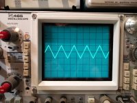
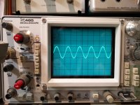
Here a few pictures. Prototype is working fine on my lab power supply, 470ma bias for 6 parallel Mosfets, 78-80ma per Mosfet (Exicon ECW10N20 & ECW10P20, selected part directly form Profusion, UK). This is a low power test, 2 Vac/1Kz into 8 ohms. Output waveforms are prefect, no oscillation, see waveforms. The output stage MOSFET are closely thermally coupled being mounted on a copper block, that is then bolted to the rear heatsink. The original Telos use the same arrangement, but thier copper block was gold plated. Mine is just protected by clear lacquer.
More to follow. Once I have a complete, runnning, assemble amp I'll update the thread...
SB
It is a long term project of mine, being working on that since the last 5 years, slowly putting together pieces of the design. I listened to a pair a few years back at the Montreal HiFi show and they sound superb! It was always a dream of mine to have a pair. The PCB design are my own, as well as the firmware. Never had a real Telos to look at. I compiled different schematics over the years, and saw the PCB silkscreen, so my parts location are close to the original. But since this is my own Firmware and control section, the rest of the amp has to match, and it is not an exact clone.
One of my problem was that the Telos use a processor and firmware to control the amp, and start, stop, switch between the different options (Mute, Analog or internal Dack, etc...) and safe shutdown in case of failure. This amp is very powefull, fast and can be prone to oscillation in some setup. So extensive protection is a must.
I wrote my own firmware using an Arduino Nano. My son a softawre engineer give me some help. The amp has sofstart (similar to Mark Johnson ACPRSS), multiple start option (Autostart on input signal, external 12V or dry contact). Mute function, etc... The small DSHP display controller, inclidng PIC code and PCB gerber came from this excellent site: HDSP 2000 Display Controller Board - Instructables
The Firmware is a State Machine, use two interrupts for the more critical faults (DC/HF & Overload) and stay in a loop after to check the remaining fault and control the amp (Mute, Digital/Analog switching, Dack Unlock/Lock indicator, etc) and the user interface (button, leds and optional display). Arduino controller is different from the original, use modern I2S interface bus and bus expanders. The Amp analog and Digital (controller) sections are completely separate and are isolated by opto-couplers. So no controller noise or dangerous analog supply levels can reach the controller.
It has more or less same interface as the original Telos: 2 buttons press power-on, 1 button for Mute, selectable Analog or internal Dac (optional), three leds for various indication (standby, Power On, Mute, Failure flash, startup sequence, etc...). I even add a small HP HDSP display module to display messages, such as Power-On, Firmware version, etc. It also display the heatsink temperature while in Mute. This small display is optional, and you'll need to get the difficult to source HDSP display. It is just nice to have since the amp is operating fine with just the leds display...
There are extensive protection and fault detection: Power Supplies Shutdown power Mosfet switches (as the original), Overload fault (using Current sensors, as the original), DC fault, HF oscillation fault, overtemp fault (an I2S temp sensor give in real time the actual temp) and speaker disconnect relay. I added a thermal AC disconnect switch in the main AC line as well as an extra thermal protection.
All these faults will shutdown the amp, a led will flash according to the fault code, and a message will be display on the display module. You need to power down completly the amp in order to clear the fault. Naturally the controller test for DC and Overcurrent faults at startup, so if a fault is still present the amp won't start...
The rear panel has Analog (SE/BAL) Input, Digital SPDIF In/Out connectors, ANA/DIG and Left/Right DAC switches, Gain selector rotary switch (-9dB, -6dB, -3dB, 0dB, +3dB, +6dB). It will also have external power On +12V or Dry Contact inputs, Chassis and Audio GND binding posts, and GND Lift switch)
Anyway this is just a preview, being working almost full time on this since th last 6 months (almost 3 months just to design the complex pcb). Presently I'm doing extensive testing, found all the pcb errors in my first prototype and finetuning the firmware. So far everything is working but I still have to check the DAC.
If there is enough interest I may offer this pcb set with controller firmware as a group buy... Kit will come with complete detailled BOM, PCB silkscreen, interconnect diagram, Spice model to look at the actual circuit behavior, voltage and current, detailled testing and startup procedure, step-by-step and per PCB. Complete kit has these PCB: Main PSU/Controller PCB, Front Panel PCB, Input/Front End PCB, Output Power PCB and a few smaller accesories PCB such as the I2S temp sensor, and optional smd to DIP op-amp adapter. The internal DAC PCB will be optional, as well as the HDSP display PCB with PIC controller.
As I said the internal dac may be an option, you can drive the amp directly from a music server, and operate in the digital domain up to the amp, as using JRiver and computer for example. The Amp has a SPDIF input and you can select what amp play Left or right channel. A SPDIF digital output then connect to the other amp. I'll make a set of DAC pcb for me, but I still need to test the prototype. Dac may also be available (all smd, very small parts design) so if you don't like smd, I guess you don't want it...
Here a few pictures. Prototype is working fine on my lab power supply, 470ma bias for 6 parallel Mosfets, 78-80ma per Mosfet (Exicon ECW10N20 & ECW10P20, selected part directly form Profusion, UK). This is a low power test, 2 Vac/1Kz into 8 ohms. Output waveforms are prefect, no oscillation, see waveforms. The output stage MOSFET are closely thermally coupled being mounted on a copper block, that is then bolted to the rear heatsink. The original Telos use the same arrangement, but thier copper block was gold plated. Mine is just protected by clear lacquer.
More to follow. Once I have a complete, runnning, assemble amp I'll update the thread...
SB
Attachments
-
 Img_1770.jpg425.7 KB · Views: 1,267
 -
 IMG_20210521_113659.jpg423.6 KB · Views: 678
 -
 IMG_20210521_113654.jpg427.2 KB · Views: 658
 -
 IMG_20210521_113647.jpg450.9 KB · Views: 706
 -
 Bias.jpg357.8 KB · Views: 809
 -
 IMG_20210521_113901.jpg624.5 KB · Views: 863
 -
 IMG_20210520_200736.jpg333.2 KB · Views: 1,190
 -
 IMG_20210520_205105.jpg387.1 KB · Views: 1,250
 -
 FAV PCB Mods.jpg952.2 KB · Views: 1,233
 -
 IMG_20210314_165244.jpg873.4 KB · Views: 1,543
Last edited:

Worked for years in test equipments repair/calibration labs. I used to service these. Nice scope when it is working, a very complex machine to troubleshoot if defective. Mine I got for cheap, was not working. Took me almost two weeks, part time, to fix. Problem was an intermittent transistor leg. All the transistors inside this scope are mounted on pcb pin sockets. This particular one was deep down inside the scope. I had to dismantle the beast a few times just to test, check, and re-assemble to test. Took forever. Being working fine since then... I have two digital scopes, but the analog ones can't be beat to see everything that's happening inside an analog circuit.
I have 6 scopes that i collected over the years: Tek TDS220, Tek 336, Tek 475, Tek SC502 (Part of the TM515 Frame), Tek 7A26/7B53AN module inside a 7403N scope frame, Rigol DS1052 (hacked to 100Mhz).
I have a very understanding wife 🙂
I have 6 scopes that i collected over the years: Tek TDS220, Tek 336, Tek 475, Tek SC502 (Part of the TM515 Frame), Tek 7A26/7B53AN module inside a 7403N scope frame, Rigol DS1052 (hacked to 100Mhz).
I have a very understanding wife 🙂
Last edited:
"but the anolog ones cant be beat------" I could have done with your input here when I was commenting on my later Tek scope --still mainly analog and was getting "shot down " by guys with the new digital--do everything "bells & whistles " scopes.
I tried to point out the definition as compared to those LCD screen types with low bit rates --no they still preferred the all singing + dancing handheld new models .
The Tek 475 I know its the , is it 200Meg version ?
No I couldn't afford those big frame jobs cost a fortune at the time but you could make many changes of modules to extend them , I still have my old Tek 2445A , wouldn't part with it never let me down .
I had a lot of the 500 series tube based -weighed a ton including the one with tube storage -- the lights dimmed when I switched on , I remember changing a 6080 in one it was a stabilized voltage of 100 volts with I think the heaters elevated to stop problems with arcing.
I too had an understanding wife didn't get jealous of my attention to my scope.
The 2445 was a great scope, I ever had the two weeks training on the series 2445/2465 at Tek in the US. Fantastic piece of equipment, but it has a few large ASIC custom modules in it, now almost impossible to find and very expensive. Also they are full of very complex digital circuits. I never had the chance to get one at a good price back then they were still top scope. These long gone days were the gold age of the analog test equipments. When I left the field autocalibration routine were starting to appears. Feed 1V, and 1Khz signal and the scope was calibrating itself automaticaly. Also replacement parts were getting harder to get, manufacturer were selleing only the main board. The service manual became just a block diagram with PCB part number. There was no fun in it anymore...
Tek465 is 100Mhz, the 475 is 200Mhz
The older Tek have more easier to source/replace transistors. If the tube don't let you down, they can almost outlive a Diyer.
Tek465 is 100Mhz, the 475 is 200Mhz
The older Tek have more easier to source/replace transistors. If the tube don't let you down, they can almost outlive a Diyer.
"there was no fun in it anymore ----" I concur --service manual became block diagram--agree , I have the original Tek operators manual.
I bought my scope from Stewart of Reading ( UK ) dealer in government electronics , at the time I got it cheap £400 he still sells the range but now -- no prices listed.
Oscilloscopes
I bought my scope from Stewart of Reading ( UK ) dealer in government electronics , at the time I got it cheap £400 he still sells the range but now -- no prices listed.
Oscilloscopes
Yes they are rather cheap these days on ebay, but I was always afraid to get a defective one. And they are heavy, so shipping cost to Canada are really bad...
SB
SB
Hi Algar,
Will you be posting schematics? I am particularly interested in the balanced input and if you have unequal impedances on the + and - legs of said input.
Regards,
Jam
Will you be posting schematics? I am particularly interested in the balanced input and if you have unequal impedances on the + and - legs of said input.
Regards,
Jam
Hi. Sorry no I won't. Only the actual GB PCB Set buyers will have access to detailled information.
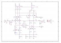
But for the record the amp input is not a real Bal to SE converter, simply terminated the V- side of the balanced input. Here a partial schematic showing the BAL to SE input... This is the case for a lot of amps that have BAL input, simulated BAL is often the case when the amp circuit is basically just SE. BAL input really makes sense only when the amp is fully balanced to start with...
SB
Attachments

"but the anolog ones cant be beat------" I could have done with your input here when I was commenting on my later Tek scope --still mainly analog and was getting "shot down " by guys with the new digital--do everything "bells & whistles " scopes.
I tried to point out the definition as compared to those LCD screen types with low bit rates --no they still preferred the all singing + dancing handheld new models .
.
You won’t catch me complaining.
I don’t own a digi’ ‘scope , but from what I’ve seen submitted by forum members, they’re almost impossible to read with any certainty the finer nuances of the trace. Maybe high end fairs better, but then at a price.
I own a 464 and a 2445. Both were free as “scrap” from a long gone test area. Scrap covered a multitude of defects, often nothing to do with their working. The latter was missing a cooling fan, so I fashioned one from a spin dryer water pump motor. The lack of a fan was probably the reason it smelt a bit. On investigation, the smell came from exploded Rifa capacitors. This failure of Rifa stuff is being commented on at the moment in the parts section of this forum.
Attachments

You could without the Arduino, but then you need a softstart circuit, and what would you do for the protection? The protection circuit is quite extensive as I said, and you need to manage the shutdown, control the supply Mosfet, speaker relay, etc...
This is a very close Telos 2500 monoblock clone. it is complex, and expensive to build. If you want just a normal Goldmund amp, without the rest, you're better to get the usual clone pcb... Keep in mind that Goldmund are notorious to be instabled, as some guy experienced with their clone on this forum. You need the correct PCB layout, correct internal wiring and ground layout, and good protection if you don't want to loose tweeters (depending on the huge area of different system, even stranger sometime in the DIY world, strange speaker cables, weird speaker crossover, etc).
I prefer to be safe and have a complete protection with this amp. HF oscillation detection in particular seems a good idea. Simpler DC protection is probably too basic to be completly safe...
And if you don't want anything too strange, build a Pass clone, inconditionnaly stable in any load, and they don't even botherwith protection, for good reason...
SB
Forgot to say that you won't have to bother with the Arduino. I won't distribute the source code. You'll get a programmed Arduino with the PCB kit. So, no real issue, assemble the main PSU PCB, insert the Arduino and start doing checks. From there you're almost done, the rest is easy...
Second amplifier channel is tested and working fine, now at 6Vac into 8 ohms, with sweep sinewave. Bias current return to the same value after thermal equilibrium and audio on or off. quite stable...
Bias stabilizes at 470ma, the heatsink is about 50C. I may add a switch on the back to select normal or low bias. A 5k6 resistor in parallel with the bias setting resistor reduces the bias to 300ma...
Indeed there is no trimmer to adjust the bias, it is set by a fixed resistor.
SB
Last edited:
Measured Bandwidth, reference 1V/1Khz into 8 ohms, -3dB at 236Khz
THD, 1V/1Khz into 8 ohms, <0.01%. This is with my prototype, and using my lab power supplies. One of the supply is switching, and has some noise on it. I may be much lower with the actual amp power supply. More to follow with my Clio measurment system...
SB
THD, 1V/1Khz into 8 ohms, <0.01%. This is with my prototype, and using my lab power supplies. One of the supply is switching, and has some noise on it. I may be much lower with the actual amp power supply. More to follow with my Clio measurment system...
SB
Last edited:
Hi. Completed the last mods, firmware corrections before assembly and test of the DAC.
So all PCB design are completed, except the DAC not tested), and Firmware Ver0.9 is functional not using the DAC option, because I can't test it at the moment.
Some more news next week.
So all PCB design are completed, except the DAC not tested), and Firmware Ver0.9 is functional not using the DAC option, because I can't test it at the moment.
Some more news next week.
Hi. First preview of an upcoming pair of monoblocks, the Goldmund Telos 2500.
It is a long term project of mine, being working on that since the last 5 years, slowly putting together pieces of the design. I listened to a pair a few years back at the Montreal HiFi show and they sound superb! It was always a dream of mine to have a pair. The PCB design are my own, as well as the firmware. Never had a real Telos to look at. I compiled different schematics over the years, and saw the PCB silkscreen, so my parts location are close to the original. But since this is my own Firmware and control section, the rest of the amp has to match, and it is not an exact clone.
One of my problem was that the Telos use a processor and firmware to control the amp, and start, stop, switch between the different options (Mute, Analog or internal Dack, etc...) and safe shutdown in case of failure. This amp is very powefull, fast and can be prone to oscillation in some setup. So extensive protection is a must.
I wrote my own firmware using an Arduino Nano. My son a softawre engineer give me some help. The amp has sofstart (similar to Mark Johnson ACPRSS), multiple start option (Autostart on input signal, external 12V or dry contact). Mute function, etc... The small DSHP display controller, inclidng PIC code and PCB gerber came from this excellent site: HDSP 2000 Display Controller Board - Instructables
The Firmware is a State Machine, use two interrupts for the more critical faults (DC/HF & Overload) and stay in a loop after to check the remaining fault and control the amp (Mute, Digital/Analog switching, Dack Unlock/Lock indicator, etc) and the user interface (button, leds and optional display). Arduino controller is different from the original, use modern I2S interface bus and bus expanders. The Amp analog and Digital (controller) sections are completely separate and are isolated by opto-couplers. So no controller noise or dangerous analog supply levels can reach the controller.
It has more or less same interface as the original Telos: 2 buttons press power-on, 1 button for Mute, selectable Analog or internal Dac (optional), three leds for various indication (standby, Power On, Mute, Failure flash, startup sequence, etc...). I even add a small HP HDSP display module to display messages, such as Power-On, Firmware version, etc. It also display the heatsink temperature while in Mute. This small display is optional, and you'll need to get the difficult to source HDSP display. It is just nice to have since the amp is operating fine with just the leds display...
There are extensive protection and fault detection: Power Supplies Shutdown power Mosfet switches (as the original), Overload fault (using Current sensors, as the original), DC fault, HF oscillation fault, overtemp fault (an I2S temp sensor give in real time the actual temp) and speaker disconnect relay. I added a thermal AC disconnect switch in the main AC line as well as an extra thermal protection.
All these faults will shutdown the amp, a led will flash according to the fault code, and a message will be display on the display module. You need to power down completly the amp in order to clear the fault. Naturally the controller test for DC and Overcurrent faults at startup, so if a fault is still present the amp won't start...
The rear panel has Analog (SE/BAL) Input, Digital SPDIF In/Out connectors, ANA/DIG and Left/Right DAC switches, Gain selector rotary switch (-9dB, -6dB, -3dB, 0dB, +3dB, +6dB). It will also have external power On +12V or Dry Contact inputs, Chassis and Audio GND binding posts, and GND Lift switch)
Anyway this is just a preview, being working almost full time on this since th last 6 months (almost 3 months just to design the complex pcb). Presently I'm doing extensive testing, found all the pcb errors in my first prototype and finetuning the firmware. So far everything is working but I still have to check the DAC.
If there is enough interest I may offer this pcb set with controller firmware as a group buy... Kit will come with complete detailled BOM, PCB silkscreen, interconnect diagram, Spice model to look at the actual circuit behavior, voltage and current, detailled testing and startup procedure, step-by-step and per PCB. Complete kit has these PCB: Main PSU/Controller PCB, Front Panel PCB, Input/Front End PCB, Output Power PCB and a few smaller accesories PCB such as the I2S temp sensor, and optional smd to DIP op-amp adapter. The internal DAC PCB will be optional, as well as the HDSP display PCB with PIC controller.
As I said the internal dac may be an option, you can drive the amp directly from a music server, and operate in the digital domain up to the amp, as using JRiver and computer for example. The Amp has a SPDIF input and you can select what amp play Left or right channel. A SPDIF digital output then connect to the other amp. I'll make a set of DAC pcb for me, but I still need to test the prototype. Dac may also be available (all smd, very small parts design) so if you don't like smd, I guess you don't want it...
Here a few pictures. Prototype is working fine on my lab power supply, 470ma bias for 6 parallel Mosfets, 78-80ma per Mosfet (Exicon ECW10N20 & ECW10P20, selected part directly form Profusion, UK). This is a low power test, 2 Vac/1Kz into 8 ohms. Output waveforms are prefect, no oscillation, see waveforms. The output stage MOSFET are closely thermally coupled being mounted on a copper block, that is then bolted to the rear heatsink. The original Telos use the same arrangement, but thier copper block was gold plated. Mine is just protected by clear lacquer.
More to follow. Once I have a complete, runnning, assemble amp I'll update the thread...
SB
Wow! I'm all eyes and ears on this project.
regards,
Marjohn
I am also stunned by the sound of GM.
After hearing the GM, I've started crazy research about it.
I am glad to see someone is organzing a TELOS project with some digital features, instead of purly analogue clone.
There are some minor differences between the Telos and Mimesis series; and I have read through several hunds of post that discuss the GM, taking note into my Onenote.
I also built a GM experimental development platform, so that I can easily modify the value or replace the parts on it to tell the difference.
I can share my note to help the community cloning the TELOS more precisely if needed, anyway, super happy to see this clone! Keep us posted!
Attachments

This schematic of this circuit on aliexpressI am also stunned by the sound of GM.
After hearing the GM, I've started crazy research about it.
I am glad to see someone is organzing a TELOS project with some digital features, instead of purly analogue clone.
There are some minor differences between the Telos and Mimesis series; and I have read through several hunds of post that discuss the GM, taking note into my Onenote.
I also built a GM experimental development platform, so that I can easily modify the value or replace the parts on it to tell the difference.
I can share my note to help the community cloning the TELOS more precisely if needed, anyway, super happy to see this clone! Keep us posted!
Hi Algar_emi,Here a few pictures.
Did you ever finish this project? The chassis are stunning. Did you make them? If not, where are they from?
Bruce
- Home
- Amplifiers
- Solid State
- Golmund Telos 2500 Monoblocks Clone PCB Set