I am really itching to replace those big can caps, both because of the age and because of the dents. I need to get on the phone with Apex Jr and see if he has a pair on the shelf that look like likely candidates. Dunno that 47,000uf like that one guy used is necessary, but i will probably go up from the original 15,200uf.
I have the DC300A manual infront of me -- the caps on this version were 13,000uF/70V
I have some Mallory CGS253U075L 25,000u/75V PM if interested.
I have the DC300A manual infront of me -- the caps on this version were 13,000uF/70V
I have some Mallory CGS253U075L 25,000u/75V PM if interested.
I don't recall exactly what the printing on the caps is, but there was a non-zero number in the hundreds place when i inspected them. *shrug*
I don't recall exactly what the printing on the caps is, but there was a non-zero
number in the hundreds place when i inspected them. *shrug*
If the rails are 60VDC, then 75V capacitors are enough. That's a 25% safety margin.
Make sure the replacements will fit mechanically.
If the rails are 60VDC, then 75V capacitors are enough. That's a 25% safety margin.
Make sure the replacements will fit mechanically.
I meant the capacitance rating. 13,500uf I think. And rated for 70 volts. So yeah 75 volt caps will be fine. And yeah, it's a narrow area.
You also have to consider the way the capacitors are mounted, using the screw terminals with nylon bushings and shoulder washers thru the chassis without any clamps. Also interesting is that early models had the capacitors on the bottom and the later models were on top, Crown basically just flipped over the chassis/heatsinks. Every time I see a DC300 posting I dream of getting mine back together, sooooo much crap so little time.
Craig
Craig

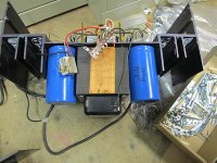
The originals on one of my DC300A's were Sangamo's, here's some pix of one (a work in process) with Mallory's fitted:
Yup, I have those white ones, with dents.
Mine are white Sangamos with dents also. Even my xfmr end bell is caved in. I tried to get a new end bell from my friend at Mercury Magnetics but it seems to be an odd size. Are all of these bottom mounted capacitors? Maybe that's why Crown swapped the chassis around on later versions.
Craig
Craig
Mine are white Sangamos with dents also. Even my xfmr end bell is caved in. I tried to get a new end bell from my friend at Mercury Magnetics but it seems to be an odd size. Are all of these bottom mounted capacitors? Maybe that's why Crown swapped the chassis around on later versions.
Craig
Thankfully the bell end on my transformer is in good shape, just the sticker is a bit damaged.
You might try to reform it - I'd try using a 2x4 (maybe trimmed down?) as an anvil, and a short-handled sledge or dead blow hammer.
Interesting circuitry, does anyone understand how it works?
I think I have figured out the basics. An op-amp drives a fairly common power-amplifier layout of the era: single ended input stage, a VAS with some kind of current-source load, a quasi-complementary triple output stage and the feedback path(s) are the thick dashed lines. But all the rest, a lot of it must be protection circuitry but what is the purpose of R213, R113, don't they introduce crosstalk or is that taken care of by Q2?
What about Q220 and R247, to me i looks like Q220 is cut off during normal operation and would only be on if there is no quiescent current but what does that protect from?
- Status
- Not open for further replies.
- Home
- Amplifiers
- Solid State
- Google has failed me - Crown DC-300A schematic?