Hi, I'm just completing my first build, amp based on F2a tube. With much help reading the forums, so thanks.
It's based on Moxtone Siemox online schematic but I've modified to monoblocks that use GZ34 rectified power supplies.
Testing had been going fine, and get B+ around where I expect, surge to 425 then settling around 380. But on a couple of occasions, on one amplifier, turning on from cold, the B+ seems to have continued to surge to 600 or more.
The first time I hit the kill switch after maybe seeing over 1000v, may have been negative (it was all quite quick, I may be mistaken). I added 1n4007 diodes and increased my first resistor to 97ohm from 47 ohm, and even swapped in a nos gz34. Seemed fine for first few times. Then one time I saw the multimeter hit around 600v and stay there. This was a different multimeter and I think its limited to 600v. I tried again later and all was fine.
I have the load wired in with 8ohm load, and valves seems to be drawing 130mA. When it starts up fine I have checked square wave on an oscilloscope and seems good.
Any ideas what may be happening here? Did I just imagine it?
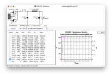
CLC using 45uF first cap. Attached PSUD pic. (Plus bleed resistor 1M not shown).
Thanks for any thoughts.
It's based on Moxtone Siemox online schematic but I've modified to monoblocks that use GZ34 rectified power supplies.
Testing had been going fine, and get B+ around where I expect, surge to 425 then settling around 380. But on a couple of occasions, on one amplifier, turning on from cold, the B+ seems to have continued to surge to 600 or more.
The first time I hit the kill switch after maybe seeing over 1000v, may have been negative (it was all quite quick, I may be mistaken). I added 1n4007 diodes and increased my first resistor to 97ohm from 47 ohm, and even swapped in a nos gz34. Seemed fine for first few times. Then one time I saw the multimeter hit around 600v and stay there. This was a different multimeter and I think its limited to 600v. I tried again later and all was fine.
I have the load wired in with 8ohm load, and valves seems to be drawing 130mA. When it starts up fine I have checked square wave on an oscilloscope and seems good.
Any ideas what may be happening here? Did I just imagine it?
CLC using 45uF first cap. Attached PSUD pic. (Plus bleed resistor 1M not shown).
Thanks for any thoughts.
Attachments
I'll add that I haven't included a standby switch to turn on heaters (since the gz34 is slow start). I'm going to guess that it may help to add one. I have read about issues from choke loaded supplies similar to this, but thought having the cap first it wouldn't be an issue.
You have a power transformer with a primary suitable to your wall power feed and a 340-ground-340 VAC secondary. You rectify its secondary output with a full-wave rectifier and you then measure up to 1000 DC? It sounds like it might be a measuring error as I can’t see how you can get a DC voltage that high from a rectified 340 Vac, even with no load on the B+ supply. Where exactly do you measure and can you calibrate your meter?

Thanks. Yes, that’s right. But it’s intermittent, ie only seen a couple of times out of say eight switch ons. I measure between my ground bar and the b+ just after the second capacitor. I won’t rule out measuring error. I’ll try some more times while videoing so I can be more certain.
High frequency oscillation can easily fool any meter.
I remember a triode connected PL504 with no grid stopper between screen and plate that seemed to defy ohm's law.
Measured cathode voltage, cathode current, screen current, plate current etc just did not go together.
Until I noticed that a digital meter another meter away with both test strips dangling free from the table went into OL each time the power was on.
The amp was a powerful RF transmitter ...
Thanks, I've done this and I'm happy I'm getting 344V acMaybe remove the GZ34 and measure the secondary of the PT on the pins there, just to reassure yourself.
I've added 1k resistors from G2 to anode on C3G drivers. (F2A already has 100ohm). I'll keep testing again over the next couple of days.High frequency oscillation can easily fool any meter.
I remember a triode connected PL504 with no grid stopper between screen and plate that seemed to defy ohm's law.
Measured cathode voltage, cathode current, screen current, plate current etc just did not go together.
Until I noticed that a digital meter another meter away with both test strips dangling free from the table went into OL each time the power was on.
The amp was a powerful RF transmitter ...
Thank you for the reply. I’m stumped and don't know what else to suggest. I guess it is likely a measurement artifact, unless you can hear the amps sounded different when experiencing this glitch. Perhaps try a different multimeter to measure the B+, video when you measure a spike/glitch. Do you have an oscilloscope to record/monitor the B+?
Once sorted out it will be a very fine set of amplifiers with (for us in the US) very expensive tubes. I’m sure it will perform very well. Best wishes.
Once sorted out it will be a very fine set of amplifiers with (for us in the US) very expensive tubes. I’m sure it will perform very well. Best wishes.
Last edited:
For reference, the schematic is derived from this one ?
http://www.moxtone.com/siemox.htm
It looks straightforward. Oscillation may happen. Do not
expect more than say 500V unloaded secondary dc, it
should be even less. High voltage seems to be a measuring
artifact if your supply ist the same as the drawing.
Where did you find the F2a sockets ?
http://www.moxtone.com/siemox.htm
It looks straightforward. Oscillation may happen. Do not
expect more than say 500V unloaded secondary dc, it
should be even less. High voltage seems to be a measuring
artifact if your supply ist the same as the drawing.
Where did you find the F2a sockets ?
Thanks all for your suggestions. I will assume it will have been oscillation. I haven't been able to reproduce the issue today (I added the g2 resistors as above). I've just tried plugging in to real speakers and they do make music! One sounded great, the other seems weak, I guess it will be difficult to get 4 matched f2a. I'll play with the bias, and I have one spare pair of tubes to try. I'm very excited about how it will sound when I get it right.
@as_audio yes, that is the schematic but supply I switched to gz34. I'll see if I get any problem going forward, but hopefully not.
I got the chinese f2a sockets and they seem fine. The originals seem almost impossible to find.
@Francois G I have an oscilloscope but I think its max is 300v so i'm staying clear of the b+.
- Home
- Amplifiers
- Tubes / Valves
- GZ34 occasional runaway voltage