Hello !
today i am presenting you quite an interesting "issue".
On the last project i needed very big power transformers, and i have ended up with two big toroids of ~1500VA each.
I was noticing that when i have some house appliances turned on, the transformers began to hum very heavily.
i have connected an hall effect current sensor in series with the primary lead that goes to the wall-socket and i have captured some wafeworms.
oscilloscope is AC-coupled and the sensor outputs 40mv/A
This is when everything is turned of. Transformer is noiseless

this is with the hair dryier turned on on HALF-setting (i think they have used some sort of diode clamping trickeroo to get less heat/less air)

needless to say, in this situation transformers are humming very badly.
quite strange... isn't it ?
the voltage waveform is almost identical in both cases...
Any ideas ?
today i am presenting you quite an interesting "issue".
On the last project i needed very big power transformers, and i have ended up with two big toroids of ~1500VA each.
I was noticing that when i have some house appliances turned on, the transformers began to hum very heavily.
i have connected an hall effect current sensor in series with the primary lead that goes to the wall-socket and i have captured some wafeworms.
oscilloscope is AC-coupled and the sensor outputs 40mv/A
This is when everything is turned of. Transformer is noiseless
this is with the hair dryier turned on on HALF-setting (i think they have used some sort of diode clamping trickeroo to get less heat/less air)
needless to say, in this situation transformers are humming very badly.
quite strange... isn't it ?
the voltage waveform is almost identical in both cases...
Any ideas ?
Hi! Ugly, really. I should kill that hair dryer.
The power outlet represent a very low impedance, so the voltage may not affects at all.
Does the hair dryer have a fixed low power level, 0-half-1? Halfwafe rectifier is a sinister solution, good designers use two filaments.
Modern gadgets often use a triac to cut the AC wave somewere, every 1/100 s (if your AC frequency is 50 Hz) to let a suitable portion of the power let through. This creates distortion, harmonics of the AC frequency and cheap things don't have much of filtering. But this is assymetric??? Could be a defect one.
You can attach a DC blocker, two big electrolytic capacitors back-to-back clamped with high current diodes antiparallel. That will probably silence the transformer.
I've found this, may be helpful: dc filter
Or kill the hair dryer.
I have the same exact problem - with a hair dryer! I have two toroids in my lab space / listening room and dedicated circuits.
These toroids are silent until my wife turns on her hair dryer at the low setting.. The buzz is very audible and terribly annoying. And yes I saw more or less the same nasty wave form..
I think in low speed mode they feed the motor half wave rectified DC.
I was able to measure a very small change in the DC content of the waveform.
In some modes the hair dryer half wave rectifies the mains so unbalances it.
A good mains DC blocker will fix the hum.
A good mains DC blocker will fix the hum.
Already tried a DC blocker.
classical Cap (back-to-back) with diodes across it.
furthermore i have tried isolating both the amp and the dryier behind an isolation transformer (non autoformer).
"different" behaviour, but still a huge problem on the current drawn by the toroids in the amp.
if i "flip" the dryer plug, the behaviour change (mirrors)
see attached

this is with the hair dryer behind an isolation transformer and plugged Live on Live an Neutral on Neutral

This is the same experiment, but with the plug "inverted", phase on neutral and neutral on phase
any guess ?
classical Cap (back-to-back) with diodes across it.
furthermore i have tried isolating both the amp and the dryier behind an isolation transformer (non autoformer).
"different" behaviour, but still a huge problem on the current drawn by the toroids in the amp.
if i "flip" the dryer plug, the behaviour change (mirrors)
see attached
this is with the hair dryer behind an isolation transformer and plugged Live on Live an Neutral on Neutral
This is the same experiment, but with the plug "inverted", phase on neutral and neutral on phase
any guess ?
Strange. I had a similar problem, the hum remains behind a DC blocker, but the > 1kVA transformer had fallen on the hard floor from a bench, so I gave it up anyway. May off topic, but I remember I saw an electrical clock reverse when I reverse the plug. AC. No ground. That should be impossible. How could it know?
So, we have an inexplicable problem. Interesting. I'm sure it has something to do with magnetostriction and saturation . I'm not really bad at physics or electronics, but this beats me.
So, we have an inexplicable problem. Interesting. I'm sure it has something to do with magnetostriction and saturation . I'm not really bad at physics or electronics, but this beats me.
You may want to measure the actual DC present on the line using an LPF as previously mentioned. It may be that you need additional diode drops?
What value capacitors did you use?
What value capacitors did you use?
What is the loading on the toroid - it appears to be a diode rectified, capacitor filtered dc supply with load on it?
Maybe the effect is mainly related to gross waveform voltage distortion, such that the dV/dt of sections of the waveform is that sustained as to make the transformer flux think it is seeing a 'dc plateau' (ie. a lower incremental frequency) and as such can't support the applied voltage.
Maybe the effect relates to waveform shape distortion (flat topping), and a non-symmetrical secondary side loading on your toroid, such that diode conduction starts as the secondary voltage increases, but then a flat-spot of the voltage waveform stops diode conduction for a while, and then the filter capacitor discharges to a point where the rectifying diode(s) start conducting again.
Was the toroid current waveform unchanged (assuming just the toroid was downstream of the blocker)?Already tried a DC blocker.
classical Cap (back-to-back) with diodes across it.
Would you have a screenshot of the toroid waveform?furthermore i have tried isolating both the amp and the dryier behind an isolation transformer (non autoformer).
"different" behaviour, but still a huge problem on the current drawn by the toroids in the amp.
Maybe the effect is mainly related to gross waveform voltage distortion, such that the dV/dt of sections of the waveform is that sustained as to make the transformer flux think it is seeing a 'dc plateau' (ie. a lower incremental frequency) and as such can't support the applied voltage.
Maybe the effect relates to waveform shape distortion (flat topping), and a non-symmetrical secondary side loading on your toroid, such that diode conduction starts as the secondary voltage increases, but then a flat-spot of the voltage waveform stops diode conduction for a while, and then the filter capacitor discharges to a point where the rectifying diode(s) start conducting again.
Hi Gionag
DC blockers and mains filters
here on post 228 plus next some other there ara additional infos
To get the right test is better to use a differential probes, in this way you can see the voltage and current.
In case I can send you the two articles from Audioreview; you are italian I suppose
Walter
DC blockers and mains filters
here on post 228 plus next some other there ara additional infos
To get the right test is better to use a differential probes, in this way you can see the voltage and current.
In case I can send you the two articles from Audioreview; you are italian I suppose
Walter
Last edited:
You may want to measure the actual DC present on the line using an LPF as previously mentioned. It may be that you need additional diode drops?
What value capacitors did you use?
I have used two 4700uf back to back with a diode bridge across it.
like that
But i have done a test also with an isolation transformer in between and nothing changed. Both the isolation transformer and the "amp" toroids buzzed heavily with the dryer on at 1/2 power
Hi Gionag
DC blockers and mains filters
here on post 228 plus next some other there ara additional infos
To get the right test is better to use a differential probes, in this way you can see the voltage and current.
In case I can send you the two articles from Audioreview; you are italian I suppose
Walter
I have not checked the DC level with a LPF on the mains, but surely i will right away.
I was testing the voltage waveform at the transformer where i read also the current and it seemed that has not changed too much with the dryier off/on.
Btw i am starting with a far from perfect sine voltage, the top is already flatten.
btw i will take more measures with the lpf and i will grab some screenshot while am at it.
thanks
Last edited:
The current spikes you are seeing are occurring when the AC input is around zero volts which is very strange. What kind of rectifier are you using? Is it a diode bridge or something active?
Brian
Brian
The current spikes you are seeing are occurring when the AC input is around zero volts which is very strange. What kind of rectifier are you using? Is it a diode bridge or something active?
Brian
Nice catch. I am using an active rectification with the LT4320.
Btw... made a measurement with the LPF filter proposed by waltube.
at "rest" the mains stabilize around 10mv of DC, when i turn on the hair dryer on half-setting, the DC level raise to 1.05V, and if i flip the plug in the socket, the amount is the same, but flips the sign (-1.06v).
Attachments


Bravo!
It is correct.
If you plug in counter position you must read - volt.
If you primary as a Rdc of 10 ohms the I is 100 mA , it is not so little if your trafo is not properly sized.
Walter
It is correct.
If you plug in counter position you must read - volt.
If you primary as a Rdc of 10 ohms the I is 100 mA , it is not so little if your trafo is not properly sized.
Walter
I am using an active rectification with the LT4320
Sounds like whatever is happening, it is causing the MOSFETs in the bridge to cross-conduct around zero volts. Are you using the recommended MOSFETs? Can you swap for a diode bridge temporarily?
I am surprised that a hairdryer set to 600W (a guess for half power) is causing this. Is there any disturbance around zero volts on the mains voltage when the hairdryer is on?
I guess that if you put more diodes in series on the DC blocker, you could solve it for the hairdryer, but you might still have problems with a different appliances
Brian
the first version of the power supply was based with MUR diodes, classic arrangment.
then, for reason not related to the humming, i have redesigned it around the lt4320+StripFet Mos. i can say that this has lowered the humming.
Just moments ago i have re-tested what happens after my dc-blocker (caps+diodebridge), and the DC is went down from 1.05v to 0.4v (... just one diode voltage drop).
So i guess is time to put some more diode's in series to each other and see what happens.
As last resort, i have seen that waltube has used 15mf caps in antiparallel without diode acros it... to what i understand, now, all the current "ripple's" in the capacitors, without any fast-passing trought the diode, but then, i guess it works with whatever dc-bias the mains has...
i will test both ways
I think we got it.
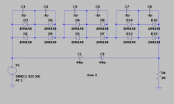
i have used two 22mf 63VDC capacitor back to back + a series with 3 x diode bridges in series.
something very like that
THAT
attached is the current version.
I have seen many other designs that has a resistor across the capacitors... what is its purpose ?
thansk folks for all the help...
i have used two 22mf 63VDC capacitor back to back + a series with 3 x diode bridges in series.
something very like that
THAT
attached is the current version.
I have seen many other designs that has a resistor across the capacitors... what is its purpose ?
thansk folks for all the help...
Attachments
Last edited:
Hello,
Have you an idea of the value of the inductance of the primary of your transformer ?
not at all, i have an LCR meter, can i use it reliably across the primary ?
at the moment the problem seem solved...
As far as i understood in my readings on the topic, the issue is more accentuated when a transformer is not loaded "enough"... and that is my very case. i have designed the transformer quite oversized...
but i want to go deep as possible on that matter... so my journey is not ended here
C1 and C2 should be back to back, not parallel. I recommend fuse, and closed grounded metal enclosure and think about placing on high side rather than neutral. (Yes operating at elevated voltage, but voltage across the components is the same. I am not comfortable with it in neutral, due to a concern about safety. )
C1 and C2 should be back to back, not parallel. I recommend fuse, and closed grounded metal enclosure and think about placing on high side rather than neutral. (Yes operating at elevated voltage, but voltage across the components is the same. I am not comfortable with it in neutral, due to a concern about safety. )
Sure, indeed i have modified my previous post as i was worried that you understood that i followed that schematic "blindly".
please see the attached schematic.
And about Neutral/live... i guess that difficult to define a-priori. In Italy the sockets and plug are reversible... and, unless you take care to put all the system/house in "phase", there's no indication about the polarity.
Last edited:
- Home
- Amplifiers
- Power Supplies
- Hair Dryiers, washing machine and a coffee grinder....