Hi all,
I've got a bit of an odd project on my hands here...
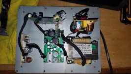
I picked up an old Harmon/Kardon SB16 powered subwoofer. It appears to work (power light comes on), but it's meant to pair with a sound bar via bluetooth, so it has no physical connections at all.
I'd like to try to hack in a set of inputs (RCA for preference) by finding a tap-in point on the board(s) somewhere. I'm sorry if this is the wrong place for this, but since the connections are all attached to the plate amp built into the sub, I thought it would be appropriate. Please feel free to move if there's a better place to discuss.
Anyway, I popped it open tonight, and got some good photos (I hope) if the internals. I can take shots of any specific angles if it will help.
I'm guessing that the wired connection, if possible, will need to be made somewhere on that board that also has the wireless module and antenna, since the other boards appear to be dedicated to power, control, amplification, etc...
I made up a simple lead with probes on the ends, and thought about hooking it up to a low-level input, like my phone, and touching various places with the sub powered up to see if I got any output, but that sounded like a very good way to fry my phone and/or the amp. 😱
Is there a better way to determine where I might be able to tap in a wired input for this?
Photos attached for reference. The first couple are just for context. More available upon request.
Thanks!
-Mike
I've got a bit of an odd project on my hands here...
I picked up an old Harmon/Kardon SB16 powered subwoofer. It appears to work (power light comes on), but it's meant to pair with a sound bar via bluetooth, so it has no physical connections at all.
I'd like to try to hack in a set of inputs (RCA for preference) by finding a tap-in point on the board(s) somewhere. I'm sorry if this is the wrong place for this, but since the connections are all attached to the plate amp built into the sub, I thought it would be appropriate. Please feel free to move if there's a better place to discuss.
Anyway, I popped it open tonight, and got some good photos (I hope) if the internals. I can take shots of any specific angles if it will help.
I'm guessing that the wired connection, if possible, will need to be made somewhere on that board that also has the wireless module and antenna, since the other boards appear to be dedicated to power, control, amplification, etc...
I made up a simple lead with probes on the ends, and thought about hooking it up to a low-level input, like my phone, and touching various places with the sub powered up to see if I got any output, but that sounded like a very good way to fry my phone and/or the amp. 😱
Is there a better way to determine where I might be able to tap in a wired input for this?
Photos attached for reference. The first couple are just for context. More available upon request.
Thanks!
-Mike
Attachments
-
 20200824_202952 (Large).jpg362.3 KB · Views: 662
 -
 20200824_202957 (Large).jpg318.9 KB · Views: 551
 -
 20200824_203154 (Large).jpg408.7 KB · Views: 784
 -
 20200824_203536 (Large).jpg486.4 KB · Views: 544
 -
 20200824_203603 (Large).jpg456.3 KB · Views: 675
 -
 20200824_203610 (Large).jpg453.7 KB · Views: 551
 -
 20200824_203629 (Large).jpg481.5 KB · Views: 504
I would mess with the cable from Wireless to VOLume. This is plain audio. There is little or no amplification on that board. I'd trace to the top of the volume control and inject signal there. It may bypass the low-pass, does that matter?
PLEASE keep your wits about you and do not get shocked in there.
PLEASE keep your wits about you and do not get shocked in there.
Attachments

Before You do more probes place a say 4.7-10K resistor in series, & eventually a capacitor I've burned a phone by connecting it to faulty mixing desk which was outputting 25VI made up a simple lead with probes on the ends, and thought about hooking it up to a low-level input, like my phone, and touching various places with the sub powered up to see if I got any output, but that sounded like a very good way to fry my phone and/or the amp.
The problem is ... probably it is nor receiving the power on signal from the sound bar and is not powering the amp. Check PCB markings for a STB signal.
@PRR: Thanks! That's an excellent starting point. Other than the actual wireless module itself, which is obviously intended to receive the incoming signal from the sound bar, what would you suspect the rest of the components on that board are doing?
I was wondering if all that was something I needed to preserve?
@MAAC0: I never connected the probe to anything, for exactly the reasons you mentioned. I didn't feel safe poking around without some sort of protection.
That's a good point about the power-on signal. When I flip the switch, the power light comes on on the front panel, but it's yellow/orange. I have no idea if it's supposed to go green when it's "active", but I suspect not, since the lead to it is only 2 wires.
Ok, update time!
I tested the driver separately with my phone and pocket bench amp, and it works just fine.
It would have been a waste to discover at some later time that the driver was blown. 😉
After poking around on the boards a bit more, I wasn't able to discover any obvious connection points, but another web search did turn up these nifty schematics!
Any of you electronics wizards able to ID a likely safe point to inject a low-level signal from these plans?
Thanks!
Attachments


All four boards are required because of how functions are split around. The "radio" board also makes clean power for the knobs/filters board, etc.
Feed CON1 on the board with the knobs. Pin 3 is signal ground. Pin 2 and pin 3 are mixed as Signal Hot, feed either or both.
As discussed, you probably have to gimmick a relay on the *AC POWER* board. This is where you can get electrocuted or burn down the house.
Feed CON1 on the board with the knobs. Pin 3 is signal ground. Pin 2 and pin 3 are mixed as Signal Hot, feed either or both.
As discussed, you probably have to gimmick a relay on the *AC POWER* board. This is where you can get electrocuted or burn down the house.
Attachments

All four boards are required because of how functions are split around. The "radio" board also makes clean power for the knobs/filters board, etc.
Feed CON1 on the board with the knobs. Pin 3 is signal ground. Pin 2 and pin 3 are mixed as Signal Hot, feed either or both.
As discussed, you probably have to gimmick a relay on the *AC POWER* board. This is where you can get electrocuted or burn down the house.
When you say "radio board", do you mean the wireless board?
I assumed that all boards are required, which is why I was trying not to bypass anything if I could help it.
Feed CON1 on the tan colored board in post #1 (eliminating the wireless board), or on the unpopulated pads visible in the lower left of the last photo, also in post #1?
I find it odd that there are 2 spots marked "CON1" on the wireless PCB. One has the connector in it that goes down to the tan preamp board. The other one is that row of unsoldered pads I mentioned. Makes me wonder if those are somehow tied together, but I can visually trace them, and I don't want to disassemble the boards further if I can avoid it.
I tried injecting a signal to those solder pads with the amp on, but I was wearing my rubber insulating gloves so I wouldn't light myself up, and it was awkward. I'm not sure I got a good touch on each pad combination. That was before I found the schematic anyway...
In regards to the standby power thing, I'm not expecting that to be an issue, since I can hear the relay kicking in and powering up when I flip the switch. I think it's just *ON* when you give it power. 😵
EDIT: Wait, what's Pin 4 on CON1 for?
Last edited:
I would say pin 2 & 4 are audio inputs.what's Pin 4 on CON1 for?
Last edited:
I would say pin 2 & 4 are audio inputs.
At which location? On the tan board with the knobs, or on the preamp board at those unsoldered pads? So far, nowhere I've injected a signal has seemed to produce any sound.
So I've attempted to inject audio into those pins, with no success.
I believe the earlier comments were correct (I'm sure you're all shocked), and the amp is in fact in "standby" mode.
Any idea how to get it out? The manual says it comes out of standby when it detects a signal. I assume this was handled through the bluetooth module, which I don't have access to. Any other obvious option? I saw a pin labeled "STNBY" on the board, but I can't recall which one off hand, and I don't see it on the schematics.
As another (more sane) option, if I rip the whole thing out and replace it with a simple 'board amp', what would be the suggestion?
I'd like to DIY/Ghetto up some solution that doesn't require an actual plate amp, since that would be too simple (ha!) and also would cost more than this thing is worth to me.
I found this little amp and power supply, but at 8ohms, I don't think it's gonna be putting out enough juice to really do that sub justice. The performance table quotes something like 38W @ 24v, 8ohms. Hmmm....
I also found this one, which looks far more appropriate, but finding a transformer/PSU to drive it is another story...
There is the xfmr in the existing amp, which I could harvest, but I don't know how to calculate to see if it's able to drive that board.
The label says it's 23.5V+/-, 2.25A, which I believe should work out to about 106VA. That doesn't even seem to be enough for the existing amp, given that the stuff I've read says you need to design for nearly double the load, but it was running a "100W" amp before, sooo....
Thoughts?

And the thread has risen from the dead! lol
Thanks, I'll give that a try next time I'm out in the shop. 👍
Thanks, I'll give that a try next time I'm out in the shop. 👍
Thanks so much for this. With the steps I had already done previously, along with cutting that 1 wire, I now have it working as a wired sub! 😀Cut the STC wire on CON2 on the wireless board, that will put it in "permanent on" mode. Then wires 2,3(sig gnd),& 4 on CON1 on the wireless board will let you send signal to the pre-amp board.
buonasera a tutti, anche io ho un sb16. purtroppo la soundbar è morta e stavo cercando un modo per usare il subwoofer. Ho letto che sei riuscito a fare la modifica. potresti postare le foto del cablaggio finale? grazie NINOGrazie mille per questo. Con i passaggi che avevo già fatto in precedenza, oltre a tagliare quel filo 1, ora lo faccio funzionare come un sub cablato!😀
good evening everyone, I also have a sb16. sadly the soundbar died and I was looking for a way to use the subwoofer. I read that you were able to make the change. could you post the pictures of the final harness? thanks NINO
Sorry, there are no photos to post. If you look back through the previous pages, you will see what instructions I was told to try. I did these, and it worked, along with the one last wire to be cut as noted in post #12.
thanks so i have to cut the stc cable and solder outside the rca connector 2 and 4 and inside the correct 3? you have been very kind
- Home
- Amplifiers
- Chip Amps
- Hard wiring a H/K SB16 wireless sub