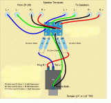
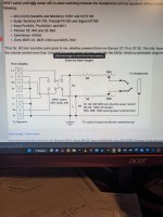
im looking for a circuit that uses a dpdt switch to alternate between speaker out and headphone out. i understand i need to make a resistor network to make the output transformer see 8 ohms but im unsure of the resistor values for a 3 watt amp. also do i need an l pad?
LPad calculator here:
https://robrobinette.com/HeadphoneResistorNetworkCalculator.htm
You could rig up a 3 position rotary switch rotary switch for 32 ohm phones, 300 ohm phones, or speakers to select between lo/high lpad resistors or none for speakers. If you get a multi-deck multi-pole rotary switch you can double up the contacts for each channel to improve the reliability of the switch, more contact surface area. Just saying cheap switches are going to be the weakest link so get a good switch.
Forgot to mention, if you use a rotary switch get a make before break type (shorting type) so the opt never loses its load. Switching an inductor suddenly to unloaded causes a spike of energy, it may not be harmful here, but this will be quieter if the switch is used while playing.
What kind of 4 Watt amplifier is this? If it's a SET without loop feedback, it can be operated safely without a heavy (8 Ohm) load, especially if you incorporate an output Zobel. This could be series'd 10R plus 0u1F, connected across the output transformer's secondary.
So, padding for the headphone output doesn't need to show the amplifier 8 Ohms. Several hundred Ohms is just fine, and allows you to leave the headphone jack live at all times. Only the speakers need be switched, and only on and off. Commercial amplifiers have been built this way since the dawn of time.
All good fortune,
Chris
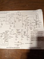
That includes an output Zobel (drawn "above" the output transformer) and is marked as stable unloaded, so should be safe to operate with just a 2-pole single throw switch to the speakers, and a higher impedance (maybe a couple hundred Ohms pad to the headphones.
All good fortune,
Chris
All good fortune,
Chris
Im torn between 2 circuits suggested by a few fellow DIYers. My knowledge is rather limited (l-pad and amplifier attenuation) so I'm hoping a few experts might chime in to explain the difference between the drawings. I'm currently designing the circuit layout) and im at the point of adding a headphone jack for the build.
its just a simple SET amp with about 4-5 watts of power. The problem is that my father wants the headphone jack to listen with his 5k $ focal utopia headphones (85 ohm impedance) that are for sure going to reveal any signal put out by my amp, good and bad.
Chris, the design does have local feedback
edit- wire wound vs metal oxide. Im having trouble sourcing non inductive wire wound resistors.
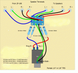
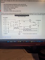
https://robrobinette.com/HeadphoneResistorNetworkCalculator.htm
its just a simple SET amp with about 4-5 watts of power. The problem is that my father wants the headphone jack to listen with his 5k $ focal utopia headphones (85 ohm impedance) that are for sure going to reveal any signal put out by my amp, good and bad.
Chris, the design does have local feedback
edit- wire wound vs metal oxide. Im having trouble sourcing non inductive wire wound resistors.


https://robrobinette.com/HeadphoneResistorNetworkCalculator.htm
Last edited:
I did a video series based off that design with the 8ohm loads. It works great and will be safe for use with any tube amp!
https://www.youtube.com/playlist?list=PLtEhh3UpOsiACD0C8pv-xTM49a7B_3-VC
This is the first video, this is a great first DIY project and the 4 videos are linked.
https://www.youtube.com/playlist?list=PLtEhh3UpOsiACD0C8pv-xTM49a7B_3-VC
This is the first video, this is a great first DIY project and the 4 videos are linked.
Last edited:
Thanks Stephe. (good videos im watching them now} ill be going with that design. I'm not sure about adding a potentiometer in line with the output after the dropping resistor. I might leave it out
Listen to Stephe.I'm not sure about adding a potentiometer in line with the output after the dropping resistor. I might leave it out
- Home
- Amplifiers
- Tubes / Valves
- headphone jack for single ended amp
