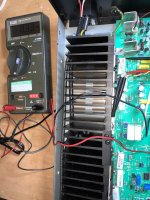
I could use a little assistance on the step-by-step to bias adjust my HCA-1000A.
I've watched a few "generic" YT videos on this for other amps and sort of get the basics, however the forum posts, videos and articles I've read have not been on this unit, or haven't provided enough detail for me. Some procedures have been close but when things state "measure from the output rectifier emitter" I sorta get lost. I know, I sound like an idiot. I just would like to learn.
I've got a DMM and some 'nads to give this a try, but I need some baby steps. If someone could point out where/what I should be placing my leads I'd really appreciate it, and then I can pay it forward someday.
Do not do this unless you are an experienced technician. It is very easy to make a short with your probes
that will severely damage the amplifier. It is better to leave the bias setting as-is. Also you would need an
expensive voltmeter and special probes that can measure a few mV accurately enough.
that will severely damage the amplifier. It is better to leave the bias setting as-is. Also you would need an
expensive voltmeter and special probes that can measure a few mV accurately enough.
Last edited:
Maybe I can get some help with setting up my DMM correctly. I’ve measure across both R127 and R227 with my multimeter set to measure current in DC. Both emitter resistors measure about this same way: 0.30 when first powered on and after a few minutes are up to around 0.70 before I power off.
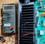
Something seems amiss. Here is a pic of my DMM and on the right is seen the clamps on the legs of R227.
Am I setting something up incorrectly? Are my DMM setting incorrect?

Something seems amiss. Here is a pic of my DMM and on the right is seen the clamps on the legs of R227.
Am I setting something up incorrectly? Are my DMM setting incorrect?

Maybe I can get some help with setting up my DMM correctly. I’ve measure across both R127 and R227 with my multimeter set to measure current in DC. Both emitter resistors measure about this same way: 0.30 when first powered on and after a few minutes are up to around 0.70 before I power off.
Something seems amiss. Here is a pic of my DMM and on the right is seen the clamps on the legs of R227.
Am I setting something up incorrectly? Are my DMM setting incorrect?
View attachment 930421
However when I change the DMM to “300mV” setting and move the input to the V/ohm/diode input the reading is around -05.0. Not sure what that means however:

Attachments
Last edited:
Oh, man you want to adjust the amplifier, but don't know to use DMM? Read the basics at least, before you burn down the amp or hurt yourself..
This one reminds me of something, when I was a kid I tried to "measure the current" sticking dmm probes directly at 220V mains... I was lucky, only large pop and smoke from the dmm.. 😀
This one reminds me of something, when I was a kid I tried to "measure the current" sticking dmm probes directly at 220V mains... I was lucky, only large pop and smoke from the dmm.. 😀
Last edited:
I have several older Parasound amps. The ones like yours with the internal heatsinks run very hot. I would set the bias at 7 mV, which is optimal based on my own distortion measurments. You need to let the amp settle in every time you make an adjustment for a stable reading. Always keep an eye on heat sink temp and output offset voltage (shouldn't be more than a few millivolts if the DC servo is working correctly). If you have more offset, you must check all output devices first, otherwise the amp won't work properly and may fail shortly.
It looks like some repaired that amp based on the off brand .33 ohm emitter resistor I see. If the amp suffered from shorted output transistors, you will want to replace the whole channel's worth as a beta matched set along with all the emitter resistors.
The bias adjustment is very touchy on these amps. Very small nudges of the bias pot make big differences. Also be aware that pots in both channels don't rotate in the same direction to increase or decrease bias.
However when I change the DMM to “300mV” setting and move the input to the V/ohm/diode input the reading is around -05.0. Not sure what that means however:
View attachment 930426
I agree with the others. If you don't know or feel comfortable with what you're trying to do, let someone qualified make the adjustments for you.
When you place the DMM in the diode setting and measure voltage drop across the emitter resistor, you're forcing the amp to absorbe the test voltage applied by the DMM. Thats not a good idea. Only measure im the 300mV DC voltage range.
I'll be the first to admit that I am a bit of a noob here, however I found some resources and find myself more comfortable. I contacted Parasound and they were quick to help with the last few questions I had.
Looking back I think the 5.0mV measurement had be a bit confused as the factory setting is 10mV with a +/-2mV tolerance which meant the 5.0mV reading was much more out of spec then I'd expected.
The pots are super touchy, good advice and I've been careful to make small adjustments. I've read that John Curl has recommended an optimal setting of 17-20mV for this amp. I've added a couple of quiet small fans as that seems pretty high to me. With the amp running for 6 hours at 17mV the heatsinks are sitting around 40C. I think for now I'll leave it at 17mV and temper that if things seem to get too toasty!
While you're in there I would replace R112 and R212 (47K neg feedback resistor) with some 47K Holco H4 resistors and get rid of the extra bypass film capacitors across the main PS filter caps. This improves the sound of the amp. I did this on my HCA1500A and was surprised at how much of a difference it made. This was recommended by John Curl himself.
I know this is an older thread, but I have a HCA-1000A. It was recapped several months ago and it needs to be biased. This forum is a little confusing to me. Inside of the there 2 white resistors slammed rt next to each other on each channel, with a test pin! Both on the rt and the left. Then on each channel there is is two test pins one in the back right near the last emitter resistor and in the front next to that emitter resistor, a total of three per channel. I understand how to use a multimeter. The problem Im having is not sure where to put my test leads and why is there two pots for each channel? Is one pot for the three transistors in the back and the other pot for the three transistors in the front? Yesterday I used the the center test pin on the red lead and the negative on the two outer pins. One at a time of course. So the negative probe went on to the back first, and adjusted that side with that pot on the same side. Then moved my negative to the upfront pin and adjusted that pot closer to the front. I did this with two MM, one for left and one for the right at the same time. I adjusted each pot until I got a 9mv reading and both heat sinks are pretty darn close in temperature. Now I dont know if this was done correctly or not?? The guy who recapped my amp said he took his reading from each pins on both channels one upfront and one in the back and put his negative on the chassis. ? This seems odd to me because why would there be three test pins for each channel if they weren’t used for bias? In this amp is there anything to adjust for DC offset? Not that I have any issues, just curious, thats all. The preamp is a Bryston as well as the DAC. My speakers are not high end but they sound good enough for awhile. I run an older pair of Paradigns 7SE,s I have upgraded the caps with some high end Dynacaps, I think? Something like that. Added a potentiometer two each speakers for the tweeters, because I can’t take anything bright sounding and finely add some nice heavy outriggers to each spk for better stability. If anyone could or has any useful information for me on the bias procedure I would greatly appreciate it. Thank you!
- Home
- Amplifiers
- Solid State
- Help with bias adjustment procedure on Parasound HCA-1000A

