I've seen a thread on here before about this same MCD360 Clarion Xover, that has a notoriously prone to failure power supply.
I was wondering if you guys can help me find a solution.
I was wondering if you guys can help me find a solution.
Attachments
-
 IMG_20241216_175606.jpg301.1 KB · Views: 46
 -
 IMG_20241216_175516.jpg250.9 KB · Views: 45
 -
 IMG_20241213_163404.jpg282 KB · Views: 43
 -
 IMG_20241213_165305.jpg279.2 KB · Views: 43
 -
 IMG_20241213_170251.jpg242.5 KB · Views: 42
 -
 IMG_20241213_170339.jpg244.7 KB · Views: 42
 -
 IMG_20241213_180835.jpg283.5 KB · Views: 42
 -
 IMG_20241213_184258.jpg268.7 KB · Views: 42

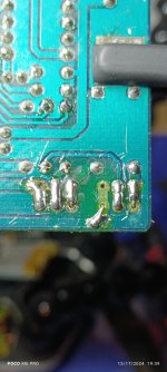
Looks like they paralleled two BJT transistors without separate emitter resistors, which is kinda stupid. Each transistor needs a separate emitter resistor (R1a R1b and R2a R2b). Alternately larger transistors instead of a pairs. Also note that 2SC9013 is only rated 20V and a P-P transformer drivers need to be at least 2x VCC, ie you need higher voltage transistors, more stupid? I might suggest a pair of BD135 ... 139.
But the real cause may be something drawing too much current, ie diodes or a chip.
But the real cause may be something drawing too much current, ie diodes or a chip.

Thank you, do you think an op-amp is drawing too much current? Or maybe the TL 494 is bad, but I checked it. And it's outputting the PWM 4 volt drive for the transistors.Looks like they paralleled two BJT transistors without separate emitter resistors, which is kinda stupid. Each transistor needs a separate emitter resistor (R1a R1b and R2a R2b). Alternately larger transistors instead of a pairs. Also note that 2SC9013 is only rated 20V and a P-P transformer drivers need to be at least 2x VCC, ie you need higher voltage transistors, more stupid? I might suggest a pair of BD135 ... 139.
But the real cause may be something drawing too much current, ie diodes or a chip.
I only have a pair of C1318 on hand, will they do? I also have to do some leg crossing.
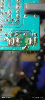
I had these MOSFETS, so I used them. I also placed 2 1k ohms resistors from pins 9/10 to pin 7 for the pulldown circuit. I used 2 100 Ohms resistors for the gate drive, but for some reason I'm only getting 1.5 volts on the gate drive. Also the oscillating frequency is over 100K.Looks like they paralleled two BJT transistors without separate emitter resistors, which is kinda stupid. Each transistor needs a separate emitter resistor (R1a R1b and R2a R2b). Alternately larger transistors instead of a pairs. Also note that 2SC9013 is only rated 20V and a P-P transformer drivers need to be at least 2x VCC, ie you need higher voltage transistors, more stupid? I might suggest a pair of BD135 ... 139.
But the real cause may be something drawing too much current, ie diodes or a chip.
Attachments
-
 IMG_20241217_192522.jpg297.8 KB · Views: 24
 -
 IMG_20241217_192919.jpg290.3 KB · Views: 22
 -
 IMG_20241217_193913.jpg304.4 KB · Views: 19
 -
 IMG_20241217_193926.jpg275.8 KB · Views: 22
 -
 IMG_20241217_201437.jpg305.5 KB · Views: 22
 -
 IMG_20241217_204654.jpg312.9 KB · Views: 25
 -
 IMG_20241217_204711.jpg214.4 KB · Views: 23
 -
 IMG_20241217_204808.jpg316.2 KB · Views: 25
The FET solution is typically the best. More work but it will never fail. I typically used a clamp with a button head screw so the crossovers (mostly Coustic crossovers) would sit flat.
The high frequency is due to the small core. Small cores require a combination of higher frequencies and more turns.
The high frequency is due to the small core. Small cores require a combination of higher frequencies and more turns.
- Home
- General Interest
- Car Audio
- Hey guys! I'm not new here, I've been a long time stalker, but now I definitely need help.