R2/C7 is standard output RC, mounted on the PS PCB from the start, but later Bonsai changed that to be soldered on the amp PCB instead.
Changes:
-R45-R47 added
-Value of R4 & R5 changed (increase current and decrease impedance)
-C18 & C19 added
-compensation caps changed to mica after doing some reading on the subject (not sure that makes any difference)
-C17 added per discussion earlier (not HF stability related, only to fix bias modulation at LF)
-input resistor network changed (personal preference for offset adjust and grounding)
Last edited:
For those of you with oscillation problems, please also decouple each 1000 uF capacitor with a 1 uF 1206 or 0805 50 V SMD capacitor.
Any reason for 1 uF rather than 100 nF ones?
For those of you with oscillation problems, please also decouple each 1000 uF capacitor with a 1 uF 1206 or 0805 50 V SMD capacitor.
I skipped that one, since I did not have any suitable caps (specs vs size), and neither did the local supplier. There's not a lot of space between the PCB and the heat sink to fit these.
Any reason for 1 uF rather than 100 nF ones?
That’s what I had available Tony and used it. If you only have 0.1uF I’m sure that will work ok.
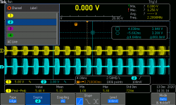
I've had some success this afternoon and gotten the amp to oscillate.
Here is a picture of it. The oscillation is coming in bursts about 2.5 milli-seconds apart (so not related to mains in any way) and the HF part is between 4 and 5 MHz.
Is this what you were seeing Tony/Bob?
Here is a picture of it. The oscillation is coming in bursts about 2.5 milli-seconds apart (so not related to mains in any way) and the HF part is between 4 and 5 MHz.
Is this what you were seeing Tony/Bob?
Attachments
Well I implemented the RC on the emitter of Q1 and 2 on one channel and that seems to have solved the oscillation problem ") Now I'll have to do that mod on the other channels also. Hopefully that is also successful. I have some household duties I must attend to so it may be a few days before I can try the mod on the other channel.
Now I'll have to do that mod on the other channels also. Hopefully that is also successful. I have some household duties I must attend to so it may be a few days before I can try the mod on the other channel.
Now I'll have to do that mod on the other channels also. Hopefully that is also successful. I have some household duties I must attend to so it may be a few days before I can try the mod on the other channel.I've had some success this afternoon and gotten the amp to oscillate.
Here is a picture of it. The oscillation is coming in bursts about 2.5 milli-seconds apart (so not related to mains in any way) and the HF part is between 4 and 5 MHz.
Is this what you were seeing Tony/Bob?
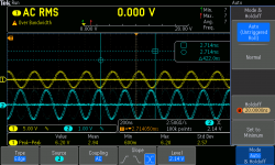
Nope, no 'wave packets' as your pics seem to indicate.
Mine was a pure sine wave at between 16 and 20 MHz seems to be identical to Bob's problem.
I'll "poke around" with a compensation network today (as per Rally's suggestions) if I have time and see what I get.
Well I implemented the RC on the emitter of Q1 and 2 on one channel and that seems to have solved the oscillation problem
Good news! Hope it works for both channels. Did you do only that one, or the other caps and resistors too?
Rally can confirm that the R/C combination works either on Q1 or Q2 emitter.
Have tried 330pF with 39R and 68R and both appear to give same result.
Have also tried 270pF and 39R and that combination works too. (reason for 270pF is because I have a few small COG lying around).
Don't have any small (1/4 W or less) resistors in < 300 ohms value and for the mod preferable to use a small resistor with the 270pF caps so I'll have to buy some.
Did you find optimum values in your experiments?
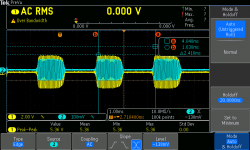
Amp connected to 8 ohm dummy and temporary 'on-board' ZN
R4/R5 still at 10K (will change to 1K or 1K2). Q1 and Q2 have 1 K resistors in their collectors (as per Bonsai)
Unfortunately the spurious waveform I get at ± 1 mV reported earlier is still there but no sign of the main (±50mV) 17-20 MHz oscillation.
Thanks for your help!
Have tried 330pF with 39R and 68R and both appear to give same result.
Have also tried 270pF and 39R and that combination works too. (reason for 270pF is because I have a few small COG lying around).
Don't have any small (1/4 W or less) resistors in < 300 ohms value and for the mod preferable to use a small resistor with the 270pF caps so I'll have to buy some.
Did you find optimum values in your experiments?
Amp connected to 8 ohm dummy and temporary 'on-board' ZN
R4/R5 still at 10K (will change to 1K or 1K2). Q1 and Q2 have 1 K resistors in their collectors (as per Bonsai)
Unfortunately the spurious waveform I get at ± 1 mV reported earlier is still there
but no sign of the main (±50mV) 17-20 MHz oscillation.Thanks for your help!
300p+??ohm on one transistor stopped the oscillation for me while probing around, but I put the RC on both Q1 and Q2, I would recommend you do the same.
I would rather go up from 330p than down.
Values are not optimized, they are just based on what I had, and some really basic simulation. I went up in capacitance to 330p and lowered the resistance from a higher value (I can't remember now) to 68 based on the stability simulations looking smoother.
Could be a good idea to let it heat up properly and check that it stays stable. Maybe check it without the output RC and load resistor too, to see that it stays stable.
I would not worry too much about the small pulses, I have the same at work, but not at home, so it was something to do with the scope or all the other stuff around. I see it on the scope measuring other stuff too. As soon as I ground the scope probe to the bench supply, it's there.
Last edited:
I just want to add that this might not be the ultimate solution to the problem, but the amp seems stable, so it's at least a way to get it playing music.
I think when Bonsai has spent some sleepless nights thinking everything through and trying ideas, he will probably come up with something more/better
I think when Bonsai has spent some sleepless nights thinking everything through and trying ideas, he will probably come up with something more/better
- Home
- Amplifiers
- Solid State
- Hifisonix kx-Amplifier