Hi!
I have a problem with the amplifier. It broke a second time and the worst part is I don't know why. The amplifier came to me with damaged transistors of the power section (IRF1010N) and the output section (IRF1310N).
When checking the power transistors (IRF1010N), I thought that the control transistors (A1015) were also damaged. I exchanged a total of 28 pieces. 12 (IRF1310N) 12 (IRF1010N) 4 (A1015)
After the whole operation the amplifier sounded and everything was ok. Large electrolytes in the filtering ones look swollen 2200uF 80V and I decided to replace them with all the others.
Unfortunately, I couldn't find the big ones, so I listed all the small ones and that's when it started ... Sorry for the long introduction, but I wanted to describe everything in detail, because it can make a difference. The amplifier stopped playing. The relay is on, the green LED is on, but the output is silent. The TIP41C transistor cannot be touched after about 15 seconds from turning on the power. The tensions on its outputs are: 1 base - 13.4V DC 2 coll - 20.3 V DC 3 emi - 12.8V DC I did some measurements and they are all described and available in the attachments.
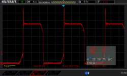
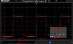
After the first repair on the GATE and DRAIN pins of the power section transistors (IRF1010N), I had an even square wave, and now it is not. Gate resistors are ok (47ohm). Voltage on 75V rails on both bridges. The supply voltage is 12.3v and limited to 2A. When TIP41C is removed, the current consumption is 1A, but when it is installed 1.4A.
I don't know why the square wave is so distorted on the IRF1010 and why this TIP14C gets so hot. I bent the output of the emitter, then it heats up slightly, but when all the outputs ... Without mounting the heat sink on it, I would not be able to make measurements with the oscillosc
I read various threads under "hifonics tip41c" but found nothing to help me fix the problem.
I am asking for help, because I have run out of ideas and I don't know what to do. 🙁
I have a problem with the amplifier. It broke a second time and the worst part is I don't know why. The amplifier came to me with damaged transistors of the power section (IRF1010N) and the output section (IRF1310N).
When checking the power transistors (IRF1010N), I thought that the control transistors (A1015) were also damaged. I exchanged a total of 28 pieces. 12 (IRF1310N) 12 (IRF1010N) 4 (A1015)
After the whole operation the amplifier sounded and everything was ok. Large electrolytes in the filtering ones look swollen 2200uF 80V and I decided to replace them with all the others.
Unfortunately, I couldn't find the big ones, so I listed all the small ones and that's when it started ... Sorry for the long introduction, but I wanted to describe everything in detail, because it can make a difference. The amplifier stopped playing. The relay is on, the green LED is on, but the output is silent. The TIP41C transistor cannot be touched after about 15 seconds from turning on the power. The tensions on its outputs are: 1 base - 13.4V DC 2 coll - 20.3 V DC 3 emi - 12.8V DC I did some measurements and they are all described and available in the attachments.
After the first repair on the GATE and DRAIN pins of the power section transistors (IRF1010N), I had an even square wave, and now it is not. Gate resistors are ok (47ohm). Voltage on 75V rails on both bridges. The supply voltage is 12.3v and limited to 2A. When TIP41C is removed, the current consumption is 1A, but when it is installed 1.4A.
I don't know why the square wave is so distorted on the IRF1010 and why this TIP14C gets so hot. I bent the output of the emitter, then it heats up slightly, but when all the outputs ... Without mounting the heat sink on it, I would not be able to make measurements with the oscillosc
I read various threads under "hifonics tip41c" but found nothing to help me fix the problem.
I am asking for help, because I have run out of ideas and I don't know what to do. 🙁
Last edited:
Measurement
I don't know why the attached files weren't added, so I'm adding them now.
I don't know why the attached files weren't added, so I'm adding them now.
Attachments
-
 HIP4080AIPZ PIN 1-5.jpg756.1 KB · Views: 131
 -
BX1500D-P.pdf66.6 KB · Views: 101
-
BX1500D-M.pdf62.9 KB · Views: 100
-
 IFR1010 DRAIN.jpg78.5 KB · Views: 72
 -
 IFR1010 GATE.jpg210 KB · Views: 68
 -
 TL494 PIN 9 AND 10.jpg212 KB · Views: 70
 -
 ZD1 DIODE.jpg210.6 KB · Views: 137
 -
 HIP4080AIPZ PIN 16-20.jpg765.1 KB · Views: 129
 -
 HIP4080AIPZ PIN 11-15.jpg761.6 KB · Views: 127
 -
 HIP4080AIPZ PIN 6-10.jpg749.9 KB · Views: 116
Regulators run hot. If you can't clamp it to the heatsink, you can clamp it to a temporary heatsink.
Do you see modulation of the square wave on pin 5 of the 4080 when you drive audio into it?
If not, check all pots and switches. One may be intermittent.
Do you see modulation of the square wave on pin 5 of the 4080 when you drive audio into it?
If not, check all pots and switches. One may be intermittent.
After applying the 1kHz signal to the input of the amplifier, I got a signal like this on pin 5 of the HIP4080AIPZ chip (attachment) I have already placed TIP41C on the heat sink, but I wonder if it is normal that it heats up so quickly and strongly.
I have a short circuit on the secondary winding of one of the main power transformers. See them on the bridges. When I unsoldered the secondary windings, the short circuit on the bridges disappeared.
I have a short circuit on the secondary winding of one of the main power transformers. See them on the bridges. When I unsoldered the secondary windings, the short circuit on the bridges disappeared.
Attachments

Don't post in all caps.
Bridges?
That signal on pin 5 should be present with or without the input.
Bridges?
That signal on pin 5 should be present with or without the input.
Probably yes, but you asked "Do you see modulation of the square wave on pin 5 of the 4080 when you drive audio into it?" That's why I connected the signal to the input of the amplifier.
Bridge rectifier
Earlier, I entered the plural by mistake, but I meant one rectifier bridge of the two.
Bridge rectifier
Earlier, I entered the plural by mistake, but I meant one rectifier bridge of the two.
That image doesn't show modulation. Is there modulation with the input?
1k is likely too high for a sub amp. Use a 50-100hZ signal.
This amp doesn't have bridge rectifiers. It has two dual rectifiers.
Using the circuit board designation, which rectifiers are you referring to as being removed?
1k is likely too high for a sub amp. Use a 50-100hZ signal.
This amp doesn't have bridge rectifiers. It has two dual rectifiers.
Using the circuit board designation, which rectifiers are you referring to as being removed?
The output transistors are currently desoldered, but modulation appears on their pads. Tomorrow I will solder them and check them and see what will come of it. I am more wondering what about this transformer and rectifying diodes D1 and D2. I guess I can't just leave it there, can I?
You seemed to say that there is a problem with the transformer. Is that correct?
Did you check D1 and D2 to see if they were shorted?
Did you check D1 and D2 to see if they were shorted?
Yes, there is a problem with the transformer. As soon as I detected this short circuit, I immediately desoldered D1 and D2 to check them, they are ok. I don't remember exactly and I can be wrong, but it seemed to me that the voltages on these four diodes are equal. The same on the two rectifier diodes for one transformer and for the other too, is it normal when the transformer's secondary windings are short-circuited?
I don't think it's a transformer problem unless when desoldering the windings, you broke a short.
In almost all instances when you suspect a transformer or inductor is shorted, it's best to troubleshoot, initially, without desoldering.
When transformers short, it's generally one of two ways. The first is a primary to secondary short. This will typically drive 12v to the secondary ground.
The second way they commonly short is primary to primary or secondary to secondary. This type of short will virtually always cause excessive current draw.
The secondary winding is only desoldered. I didn't cut out the transformer or bend the windings. Excessive power consumption (or so it seems to me) causes TIP41C and maybe that's why it heats up so much. The diagram shows that the TIP41C is powered by a separate small transformer. The problem with TIP41C is unlikely to be related to a short circuit in one of the two main power transformers. I already installed a compact transformer 2x and I was wrong 2x, this one is the third.


Without moving the wire with your meter probe, what is the resistance between the wires and the pads?
Just slight movement of the board, slight pressure on the transformer or simply setting the board down on the bench likely makes the connections reconnect, at least intermittently. That method is rarely successful or reliable.
I don't have photos of this amp board but it likely uses extra windings, not an extra transformer to power the 12v regulator.
Is the 4080 IC getting hot?
What is the DC voltage on pin 15/16?
I don't have photos of this amp board but it likely uses extra windings, not an extra transformer to power the 12v regulator.
Is the 4080 IC getting hot?
What is the DC voltage on pin 15/16?
- Home
- General Interest
- Car Audio
- Hifonics BXI-1600D second fail (no sound)