As always, you're right Perry. 🙂 Indeed, the transformer has the tap you mentioned and it powers the TIP41C. A short circuit on the rectifier pads occurs only when the transformer is in the circuit. I will upload a few photos. I do not know competently where this short circuit comes from. 4080 is slightly warm.
PIN 15 - 12.8VDC
PIN 16 - 12.9VDC
PIN 15 - 12.8VDC
PIN 16 - 12.9VDC
Attachments
-
 rsz_20210908_175725.jpg942.7 KB · Views: 81
 -
 rsz_20210908_182043.jpg940.6 KB · Views: 70
 -
 rsz_20210908_181915.jpg937.7 KB · Views: 67
 -
 rsz_20210908_180637.jpg940.5 KB · Views: 80
 -
 rsz_20210908_175948.jpg939.9 KB · Views: 76
 -
 rsz_20210908_175906.jpg942.5 KB · Views: 68
 -
 rsz_20210908_175706.jpg940.4 KB · Views: 77
If the outputs failed, it may have damaged the 4080. If it's defective, it could be why the 12v regulator (TIP41) might be running hotter than normal.
With the transformer in the circuit, you should read 0 ohms across any 2 of the 3 large secondary windings in any combination. You should also read 0 ohms across the rectifiers' outer legs (transformer in the circuit).
When the transformer is out of the circuit, none of the connections above should read anything near 0 ohms.
I thought that the HIP4080 could have an effect on the temperature of TPI41C. I checked it some time ago and from what I remember it was also heating up even when the HIP was dismantled and that's why I keep mentioning it (TIP41C).
I don't know if I understood correctly. It turns out that the measurements that are in the pictures (it is about the desoldered transformer) are correct? And the measurements of the one that was not touched are wrong? Each of the two transformers has one primary and two secondary windings. What kind of third are you talking about? Forgive me, but I don't understand everything yet. 🙁
I don't know if I understood correctly. It turns out that the measurements that are in the pictures (it is about the desoldered transformer) are correct? And the measurements of the one that was not touched are wrong? Each of the two transformers has one primary and two secondary windings. What kind of third are you talking about? Forgive me, but I don't understand everything yet. 🙁
Attachments
Images with the meter...
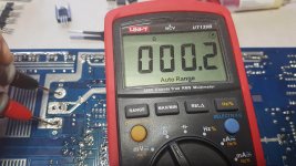
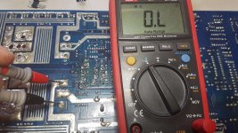
1. OK
2. bad. It looks like you have an open connection, possibly a broken winding on the transformer.
3. OK
4. bad
5. normal if transformer windings are shorted to their unsoldered pads.
1. OK
2. bad. It looks like you have an open connection, possibly a broken winding on the transformer.
3. OK
4. bad
5. normal if transformer windings are shorted to their unsoldered pads.
So I have correctly deduced from your statement that the problem lies in the second transformer. The one I haven't touched.
5 -
yes, the windings are in contact with the pads, but what about the TIP41C, which is powered by a desoldered transformer.
It is powered from the additional tap you mentioned.
5 -
yes, the windings are in contact with the pads, but what about the TIP41C, which is powered by a desoldered transformer.
It is powered from the additional tap you mentioned.
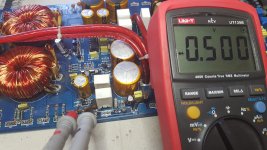
Yes, and behind them is my favorite hot TIP41C. On these diodes I have a voltage drop to 1V when the transformer is in the circuit.
It was about the voltage drop across these diodes when the transformer is in the circuit. Is this voltage drop too high? Maybe that's why TIP heats up so much.
Attachments

Last edited:
Readings in the circuit aren't definitive. The diode doesn't appear to be shorted and is likely OK.
It's very unlikely that the diodes would be contributing to the TIP41, which may be completely normal. Regulators run hot. In some amps, if the regulator isn't clamped to the heatsink, it will fail within seconds, doing extensive damage to virtually everything connected to it.
How much does the TIP41 heat up when clamped tightly to the heatsink?
How much less does it heat up with the 4080 out of the circuit?
Now, when I soldered the transformer, I have 40V on diodes D101 and D102. My hands are dropping ... 34V on the first pin TIP41C and 40V on the second pin. I think I'm going to throw it out the window soon, because my patience is running out. Now Tip41C reaches 80 degrees Celsius in 20 seconds.
Update: My mistake, I was skipping the windings. 🙁
Update: My mistake, I was skipping the windings. 🙁
Last edited:
After the windings were properly soldered, everything returned to normal. Tip41C's temperatures and heat-up speed are the same whether HIP is in the circuit or not (62 degrees Celsius for 10min - the output transistors are desoldered)..
The current consumption from the laboratory power supply shows a 30mA difference between the connected and disconnected HIP.
The current consumption from the laboratory power supply shows a 30mA difference between the connected and disconnected HIP.
Last edited:
How much does the TIP41 heat up when clamped tightly to the heatsink?
Didn't you previously state that the 4080 had 12.5v on pin 15/16?
Didn't you previously state that the 4080 had 12.5v on pin 15/16?
PIN 15 - 12.8VDC
PIN 16 - 12.9VDC
The heat sink that I installed is small. The amplifier case is many times bigger and it will dissipate heat better with TIP41C. Before I put the whole thing into the housing, I will desolder the second transformer and try to unwind the winding a bit to look for a break in the winding.
You can't have more than about 14v on leg 1 of the TIP41.
All you have to do is to clamp the TIP onto the heatsink alone. I don't think there is anything wrong with the TIP and the 12v regulator circuit. The output seems to be perfectly normal.
All you have to do is to clamp the TIP onto the heatsink alone. I don't think there is anything wrong with the TIP and the 12v regulator circuit. The output seems to be perfectly normal.
More than 14V on pin no. 1 TIP41C is possible. It is enough to badly solder the windings and desolder the D100 diode (diagram). I fixed this stupid bug and now on pin no. I have 13V on the 1 and 20V on the second, the third pin is 12V. Probably the one with TIP41C is ok, and I clung to it unnecessarily.
- Home
- General Interest
- Car Audio
- Hifonics BXI-1600D second fail (no sound)