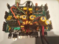
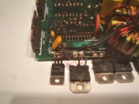
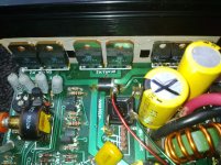
hello i made measurements without the tip35 without the resistance of 10 ohms
B + 13.07 dc
B + on remote
the amp works 1.26 amperes
--- output hp 2.71 volts dc -----
reading of measurements B + B- 13.07 volt -zero ampere without remote
on tip100 transistors + 6 tip35 and tip 100
from the right to the left
tip100: 1 13.05volts dc 2: 13.05volts dc 3: 13volts ac
tip35: 1 13.03volt dc 2: 13.05 volt dc 3: zero volt
tip35 1 13.06volt dc 2: 13.06volt dc 3: zero volt
tip35: 1 13.06volt dc 2 13.06volt dc 3: zero volt
tip35: 1 zero volt 2: 13.06volt dc 3: zero volt
tip35: 1 zero volt 2: 13.06volt dc 3: zero volt
tip35: 1 zero volt 2: 13.06volt dc 3: zero volt
tip100: 1 zero volt 2: 13.05volt dc 3: zero volt
measurement on diode bridge:
ac + 26.80volt dc
ac- -21.80volt dc
dc: 2.62 volt
dc: 2.62volt
if i weld the tip35 the fuse burns without b + on remote
the resistance 10 ohms burns
Is the first TIP100 shorted?
To measure the DC voltage on the rectifiers or the outputs, you may need to use the RCA shield or the secondary center tap for the reference (black probe).
As a side note,
tip100:
1: 13.05volts dc
2: 13.05volts dc
3: 13volts ac
tip35:
1: 13.03volt dc
2: 13.05 volt dc
3: zero volt
is much easier to read than
tip100: 1 13.05volts dc 2: 13.05volts dc 3: 13volts ac
tip35: 1 13.03volt dc 2: 13.05 volt dc 3: zero volt
the tip100 is good
I redo the measurements B- on black RCA shield
B + 13.20 volts dc
zero ampere
remote off
TIP100:
1: 6.39 volts dc
2 10.18 volts dc
3: 10.48 volts dc
TIP35
1: 10.48 volts dc
210.48 volts dc
3: -2.61 volts dc
TIP35:
1: 10.48 volts dc
2: 10.48 volts dc
3: -2.26 volts dc
TIP35:
1: 10.48 volts dc
2: 10.48 volts dc
3: -2.61 volts dc
TIP35:
1: -2.62 volts dc
2: 10.48 volts dc
3: -2.62volt dc
TIP35:
1: -2.62volt dc
2: 10.47 volts dc
3-2.62 volt dc
TIP35:
1: -2.53 volts dc
2: 9.38volt dc
3-2.62volt dc
TIP100
1: -2.54volt dc
2: 9.50volt dc
3: -2.56 volts dc
----------------------------------
I redo the measurements B- on black RCA shield
B + 13.20 volt dc 0.90 ampere
remote on B +
TIP100
1: 13.20volt dc
2: 13.20volt dc
3: 13.20volt dc
TIP35:
1: 13.19volt dc
2: 13.20volt dc
3: zero
TIP35:
1: 13.19 volts dc
2: 13.19 volts dc
3: zero volt
TIP35:
1: 13.19 volts dc
2: 13.19volt dc
3: zero volt
TIP35:
1: zero volt
2: 13.19volt dc
3: zero
TIP35:
1: zero
2: 13.18volt dc
3 zero
TIP35:
1: zero
2: 13.26volt dc
3: zero
TIP100:
1: zero
2: 14.22 volt dc
3: zero
diode bridge :
+ 31.40volt dc
-31.41 volts dc
1.70 volts ac
1.71 volts ac
I redo the measurements B- on black RCA shield
B + 13.20 volts dc
zero ampere
remote off
TIP100:
1: 6.39 volts dc
2 10.18 volts dc
3: 10.48 volts dc
TIP35
1: 10.48 volts dc
210.48 volts dc
3: -2.61 volts dc
TIP35:
1: 10.48 volts dc
2: 10.48 volts dc
3: -2.26 volts dc
TIP35:
1: 10.48 volts dc
2: 10.48 volts dc
3: -2.61 volts dc
TIP35:
1: -2.62 volts dc
2: 10.48 volts dc
3: -2.62volt dc
TIP35:
1: -2.62volt dc
2: 10.47 volts dc
3-2.62 volt dc
TIP35:
1: -2.53 volts dc
2: 9.38volt dc
3-2.62volt dc
TIP100
1: -2.54volt dc
2: 9.50volt dc
3: -2.56 volts dc
----------------------------------
I redo the measurements B- on black RCA shield
B + 13.20 volt dc 0.90 ampere
remote on B +
TIP100
1: 13.20volt dc
2: 13.20volt dc
3: 13.20volt dc
TIP35:
1: 13.19volt dc
2: 13.20volt dc
3: zero
TIP35:
1: 13.19 volts dc
2: 13.19 volts dc
3: zero volt
TIP35:
1: 13.19 volts dc
2: 13.19volt dc
3: zero volt
TIP35:
1: zero volt
2: 13.19volt dc
3: zero
TIP35:
1: zero
2: 13.18volt dc
3 zero
TIP35:
1: zero
2: 13.26volt dc
3: zero
TIP100:
1: zero
2: 14.22 volt dc
3: zero
diode bridge :
+ 31.40volt dc
-31.41 volts dc
1.70 volts ac
1.71 volts ac
It may be easier to connect a jumper between the secondary center-tap and the primary ground to prevent confusion.
For any TIP transistor that has the base more than about 0.6v greater than the emitter, it's open base to emitter. At least 3 of the TIP35s appears to be defective.
For any TIP transistor that has the base more than about 0.6v greater than the emitter, it's open base to emitter. At least 3 of the TIP35s appears to be defective.
you are right Perrry Babin!
i changed the 3 tip35
repaired the tracks
12.72volt to 0.90 ampere
in 2-channel mode the amp does not heat up
in bridge mode: 12.7volt dc -4 amperes
4ohm signal cinch20hz
speaker output set to 4volt 20hz
on the side where there are 3x tip105 at 35 ° Celsus
2xtip141 are very hot at 65 ° C
2xtip146 at 35 ° C
the tip105 are powered by 30volt dc
the tip141 and tip146 powered in 2.85 volt dc
the 4 resistances of 0.22 ohm 3 watts in 2.85 volts dc
if you have manual service?
Thank you for your help
I think this a class G amplifier. If so, the rail voltage going to the output transistors should be switched at various power levels. Something like the attached image. The switching would be done by the TIP100/105s standing in groups of 3.
If the switching by the standing TIPs isn't happening as it should (due to a shorted TIP100/105, it could cause uneven heating of the outputs.
The bias may be too high if the outputs heat up at idle.
I don't have a diagram or service manual for this amp.
If the switching by the standing TIPs isn't happening as it should (due to a shorted TIP100/105, it could cause uneven heating of the outputs.
The bias may be too high if the outputs heat up at idle.
I don't have a diagram or service manual for this amp.
Attachments
Unless you can get specific information from the manufacturer (ZED?), adjust as shown below:
http://www.bcae1.com/temp/ausettingbias.swf
http://www.bcae1.com/temp/ausettingbias.swf
hello i found this document at zed audio
he talks about serie VI hifonics in class G
View attachment zed audio amplifier classes.pdf
mail zed audio
he talks about serie VI hifonics in class G
View attachment zed audio amplifier classes.pdf
mail zed audio

- Status
- This old topic is closed. If you want to reopen this topic, contact a moderator using the "Report Post" button.
- Home
- General Interest
- Car Audio
- hifonics odin VI burned


