Solid state is far simpler - just control VAS saturation and design the whole circuit to determine which stage overloads first. I don't understand why some designs use boosted rails for the IPS ..the last thing you want is for the actual output devices to saturate first. All my amps - the VAS will clip >3V short of the rails , the OPS never saturates. I lose a whole 5V on my Hawksfords !!
You make a very good point, in the case of a BJT ops, but for a lateral fet ops, it might be sonically benificial to have the ops saturate before the front end does.
Try it out and hear it for yourself, get back to me 🙂
If I am really bored, not much chance of that these days, I could boost the AFE on my DH-200C that @anatech has in his possesion, he can do it too if he so desires. It would be good to compare the clipping behavour of the design with and with-out boosted rails. Might be an idea in a new PS design.
I assume the older japanese designs used regulated V front ends as a solution to PSRR, vs using more parts for current sources etc. They needed regulated supplies for the discrete low level ckts anyways, so start high and work your way to lower voltages.
I recreated the amp pcb (AWH-048) for the old Pioneer SX-1250, (electrically equiv) it uses regulated +/-65V, a resistor for the tail I, instead of a CCS. They used two 470uF/80V ecaps which is more expensive than the parts for the CCS. The model down, SX-1050 uses a CCS for the IPS tail cuurent, only used 220uF/63V ecaps, so different designers use different circuits to achieve the same specs, as long as they are in budget etc....
jfets and lateral mosfet output stages, so they say. if you think the o/p transformer matters, use that in your bjt design, cost vs effectIs there any transistor amplifier that is very close to tube amplifier?
Last edited:
And lots of transistor sets….Wg-ski sir your are very lucky.
You have valve amplifier.😯
Attachments


Losing 5V out of an 80 volt rail is no big deal, the same on a 25V rail can be a non starter. Having the VAS clip clean, short of the rail with an output triple is the recipe for iron fist bass. No conducted ripple in clipping, and maintaining the local negative feedback in the triple EF keeps the DF high even when you’re hard clipping. That is more important than eliminating one microsecond of rail sticking!All my amps - the VAS will clip >3V short of the rails , the OPS never saturates. I lose a whole 5V
on my Hawksfords !!
PS - on a valve amp , the output trafo contributes greatly to the "sound" . It can also saturate....
You need a transparent OPT that doesn’t saturate under operating conditions in a tube amp. If you don’t, the bass is mush. You just need to make it big enough. Those 280W Hammonds are being run at only 210W.
transferfunction posted a commercial design here https://www.diyaudio.com/community/threads/idiosycratic-amplifier-design-performance.408738Is there any transistor amplifier that is very close to tube amplifier?
The solid-state amplifier was made "tube-like" by giving it high output impedance, relatively high distortion, and hum.
Ed
I used to build my own high bias AB amps. They were very good, but it was alot of work to match output devices, input pairs, etc. When I needed a backup amp to test speakers with, I ended up buying a used Parasound A21 from ebay.
After listening to the A21 for the first time it I was quite surprised how good a used off the shelf amp could sound, plus it would effortlessly run a pair of hard to drive Soundlab electrostats.
For the price of a used A21, there was no way I could come close building my own. I was so impressed that I bought a JC5 and a JC2 preamp a few years later when I could afford them. To this date I haven't heard anything that much better aside from a pair of custom built 50W class A triode mono blocks. These cost the owner several thousand just in parts including the tubes.
Building your own stuff is fun, but its not easy to do if you want the best sounding design available. The biggest issue is spotting counterfeit parts when looking for obsolete transistors. I've been screwed a few times with this and it really spoils the fun.
That is true, but I have seen too many designs on this board that do not have good tracking between the complementary halves. They "work" only if the components are perfectly matched.Wish more DIY'ers would build symmetrical designs. Many advantages , better PSRR , general clipping.
Ed
FET driven bipolar output stages are nice if built with currently available parts. I see many designs with tube input stages, but they're usually noisy and use expensive tubes to get clean sound. Some of the Moscode stuff was nice with mosfet outputs.

I agree, but if you look at the evolution of the Krell device back under Dan, it was more concerned with temperature control of parameters. I really prefer amplifiers with a symmetrical topology, but for the most part, all the amplifiers assembled by friends had problems with optimal modes and temperature dependence of parameters. Even the Bailey multiplier in its simple form gives a temperature gradient of more than 20%, with such values any parameters will “float”. Optimization of modes and less dependence on temperature is what the amplifier needs, also more spacious housings for ventilation, there is a big difference in the quality of the amplifier in close quarters and a compact arrangement inside the housing and a spacious arrangement of blocks and elements in the amplifier housing.That is true, but I have seen too many designs on this board that do not have good tracking between the complementary halves. They "work" only if the components are perfectly matched.
Ed
My friend from Saarbrücken, for about 10 years admired a hybrid on a lamp with an output power mosfet, they almost forced them to make an input stage on transistors (diamond buffer) with an interstage transformer and power mosfet transistors (circletron), now for the last 10 year he has been admiring just such an implementation ))), everything is relative.FET driven bipolar output stages are nice if built with currently available parts. I see many designs with tube input stages, but they're usually noisy and use expensive tubes to get clean sound. Some of the Moscode stuff was nice with mosfet outputs.
SMD can reduce the price considerably. Infidel input stage costs @15$ , Output stage is 20-30$ . 30$ could be bigger MJL BJT's for 120W+ power.For the price of a used A21, there was no way I could come close building my own.
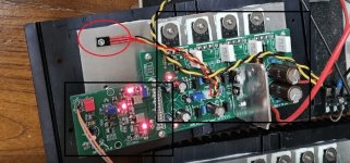
Those ON dual 5551/5401 SMD and Toshiba LTP SMD duals are spot on , (below - infidel) IPS was <1mV offset before trimming ! My "Leach" (spook) uses these sameThat is true, but I have seen too many designs on this board that do not have good tracking between the complementary halves. They "work" only if the components are perfectly matched.
SMD duals plus it self - adjusts the CCS's. "Spook" just has one adjustment for VAS LED current. 2X LED thermally offsets the Hawksford and the LED CCS's
thermally cancel. Just uses 17mA per rail (IPS) , runs so cool - just a HV op-amp made with SMD.
"spookyamp" pretty much nails the tube sound with it's rounded clip. Real mellow smooth .... smooth sound at listening levels.
OS
Attachments


You've joined this forum resently and probably not looking for older posts, but there a quite fuw good amps presented here.Awaiting when somebody will write something like: JLH 1996/2001 ESL Edition (with 2 pair of output transistors) or something. 🤣
One of them is this one: https://www.diyaudio.com/community/threads/200w-mosfet-cfa-amp.243481/
Or this one: https://www.diyaudio.com/community/threads/thermaltrak-tmc-amp.182554/
As long as the circuit has this sensor (attachment) operating in analog mode in the voltage amplification circuit, there will always be thermal modulation and the amplifier will not be high-end levelMy "Leach" (spook) uses these same
Attachments
, but there a quite fuw good amps presented here. ....Or this one: https://www.diyaudio.com/community/threads/thermaltrak-tmc-amp.182554/
You have simple, classic diagrams, but please look at the attachment.
Attachments

What do you mean by that ? This is just the "mini wolverine OPS"- #2 on the planet ... read the wolverine thread. #1 is the halcro.As long as the circuit has this sensor (attachment) operating in analog mode in the voltage amplification circuit, there will always be thermal modulation and the amplifier will not be high-end level
That is the OPS Vbe - BTW - not connected to the VAS ! , yes ... there is always short term Tc modulation on a typical Vbe (in a typical BJT junction).
. Even a NJL thermaltrak has some (but less). I'm scared NJL could become obsolete . Maybe you could give us a better example of a "high end" Vbe ?
On LT , if you hook to a voltage source (+) and specify a (-) value , it will be negative. No error there.You have simple, classic diagrams, but please look at the attachment.
He did not do that on voltage source (V8) and hooked (+ @ 50V) to earth. That one would be -50V.
You can do it either way. hooking to the (+) allows parasitic properties to be added to the source.
Edit - I suppose you could consider the Vbe as a VAS component , since it is fed from the VAS ?
Also , the little "infidel" IPS should be real close to it's big brother (below) Most likely <10PPM , uses the same
TMC but omits the CM helper and has a simple LED VAS CCS. Big brother (Wolverine) is <1PPM ! Not "high end" ??
OS
Attachments

Last edited:
Its right. The volatage source has -45V. (minus!)You have simple, classic diagrams, but please look at the attachment.
for example, the simplest is Vbe powered by a separate “weighted” voltage sourceMaybe you could give us a better example of a "high end" Vbe ?
If Vbe is in the AC voltage amplification circuit, can it be considered a high level?Big brother (Wolverine) is <1PPM ! Not "high end" ??
one hope is for the depth of negative feedback - at least 90 dB deep at a frequency of 20 kHz - I think this is a separate class of amplifiers as “ultra deep NFB”
Vbe is typically at the beginning of the current stage (EF2/EF3). Simple shunt regulator (with some gain).If Vbe is in the AC voltage amplification circuit, can it be considered a high level?
any, even small, gain of a nonlinear element inside the NFB loop requires frequency correction.Simple shunt regulator (with some gain).
- Home
- Amplifiers
- Solid State
- High quality class AB 100 watt amp