Hey guys:
Please help. I mounted every elements on the PCB, initially run at +-18V
it worked and play music well, volatge between 0.47R is about 0.8~1VDC .
However, when it went to 21.5V, the 0.47R got really hot and almost burnt, now the voltage is 3~5VDC!!
I have checked all the details, just can't get them on the right volts and work.
Any comments?
You probably cooked the 0.47ohm with such a high bias and damaged it. I would replace it by a more powerful one, ex 0.47ohm,10W or simply use 2 x 1ohm, 5W in parallel.
Keep us posted.
BR,
Eric
Keep us posted.
BR,
Eric
Hey Eric,
the burnt 0.47R one is already 5W, anyway, I've ordered 10W on the way.
But my point is, why the voltage goes highly to 5VDC?!
It doesn't make any sense, cuz this means a 10A current through it! I even suspected a short-circuit!
Regards,
erikovsky
the burnt 0.47R one is already 5W, anyway, I've ordered 10W on the way.
But my point is, why the voltage goes highly to 5VDC?!
It doesn't make any sense, cuz this means a 10A current through it! I even suspected a short-circuit!
Regards,
erikovsky
Maybe your 0.47ohm has increased it's value with such overheating, can you measure it with an ohmeter. I could be another problem.
Thanks!
Making a lot of sense! MY DMM reads are 0.7R, though I don't that believe it under such a low level of measuring. A 10W replacement seems very reasonable 🙂
Making a lot of sense! MY DMM reads are 0.7R, though I don't that believe it under such a low level of measuring. A 10W replacement seems very reasonable 🙂
I use 10W 0.5R now. Very upset, nothing is going well.
The cross 0.5R volt is 8.2V, and the 500R trimmer get very hot.
I almost give up this design, really sad
The cross 0.5R volt is 8.2V, and the 500R trimmer get very hot.
I almost give up this design, really sad
Something else seems to be going wrong.
Can you post your schematics with the measured voltages ?
Don't give up it's a very nice sounding amp.
BR,
Eric
Can you post your schematics with the measured voltages ?
Don't give up it's a very nice sounding amp.
BR,
Eric
I use 10W 0.5R now. Very upset, nothing is going well.
The cross 0.5R volt is 8.2V, and the 500R trimmer get very hot.
I almost give up this design, really sad
You better to write a book: "How convert very good amp to very crappy amp".😱😀😀😀😛
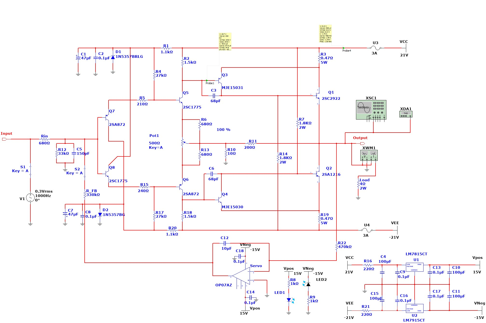
Based on your schematic:
diyAudio
I think you can lower R2 = R18 to 1K like origin schematic.
Then start rolling R4 = R17 from about 100K -> 20K (may be lower) to get the desire bias current. This is how a friend of mine success with his Hiraga 30W.
This amp not needed crappy dc servo.😛 My Hiraga's 20W has DCout floating +-5 mV, BIAS 1,3A+-20mA

HI ALL
i have built the hiraga super, is working with +/- 30v and as well with +/-36v.
every thing is getting hot, but the sound is great.
the pcb is from jim's audio hk, using output pwr mjl3281a/1302a.
simul. with spice is not great but in the real life has a great sound.
you all should try it.
Cheers,
Williams
Hi.🙂
It's very good amp for ESL. I didn't see that any amp was absolutely stable on capacitance load (6 om+2,2uF). On Martin Logan Electromotion sound much better than different class AB amplifiers with THD 0,00000005%.😀😀😀😀
(My Hiraga's 20W with small filter 0,885F http://www.diyaudio.com/forums/solid-state/193-hiraga-20w-class-95.html#post4568258)
There is absolutely nothing wrong about using a DC servo, even if it ultimately isn't necessary for correct operation. It will have no negative impacts.This amp not needed crappy dc servo.😛 My Hiraga's 20W has DCout floating +-5 mV, BIAS 1,3A+-20mA
I think there are two issues to be aware of when using a DC servo. Sometimes if the DC offset is large the DC servo will hit its rails before adjusting the amps output sufficiently. This will guarantee a DC offset. This is however unlikely to be the case here since the DC offset should be well below 1V.
If the DC servo breaks then you will get the sort of symptoms the builder is describing and then the only solution is to replace the Opamp and test again.
However when we see large voltage drops over the current sensing resistors the most likely cause is fried transistors somewhere in the chain. Unfortunately in such cases the only way to be certain is to desolder the transistor and test it out of circuit. Any builder of these circuits should expect a few frustrating hours of fault finding and a handful of dead transistors along the way. The only hope is that the expensive components don't go down. I had to track down replacement Jfets when I fried the ones in my build.
Shoog
I don't know what need to do that this amp had exploded.😡 Hiraga's 20W/30W like as Kalashnikov assault rifle from the world of amplifiers.🙂
Something else seems to be going wrong.
Can you post your schematics with the measured voltages ?
Don't give up it's a very nice sounding amp.
BR,
Eric
Hey Eric:
I just found that the resistance between +21V and GND is about 160R, I think that suggests something wrong, also, the -21&GND is ~2K
So I will start a new board assembly.
thanks
erikovsky
Thats classic fried transistor behaviour. Take out the transistor and test it.Hey Eric:
I just found that the resistance between +21V and GND is about 160R, I think that suggests something wrong, also, the -21&GND is ~2K
So I will start a new board assembly.
thanks
erikovsky
Shoog
Well caught and good luck.
Check the board for solder bridges, transistors usually go down for a reason.
Shoog
Check the board for solder bridges, transistors usually go down for a reason.
Shoog
Here is mine !
2SK170/2SJ74 (8mA)
2SC2240/2SA970
2SC2705/2SA1145
NJW0281G /NJW0302G
And I changed the front end gain resistors to 510ohm for a bias of about 0.85A
I found a set of the output pcbs I used in my le monstre as well as a custom 4x12V R core transformers I have no use for these so 35€ for the two pcbs and the transformer + shipping
- Home
- Amplifiers
- Solid State
- Hiraga "Le Monstre"