Hornresp Update 5740-250413
Hi Everyone,
CHANGE
Previously a mass loaded transmission line loudspeaker design template generated using the Input Wizard had four segments, with the third segment being 0.01 cm long to act as the interface between the end of the transmission line and the port tube mass loading (see Attachment 1). The MLTL design template now has three stepped segments (see Attachment 2).
BUG FIX
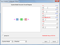
With a bass reflex design if the green fundamental frequency marker was added to the loudspeaker wizard charts (see Attachment 3) and the Schematic or System Model option then selected (see Attachment 4), when the Lpt label was double-clicked to include or remove the end correction the Helmholtz resonance frequency value was not being updated (see Attachment 5). This has now been fixed (see Attachment 6).
Kind regards,
David
Hi Everyone,
CHANGE
Previously a mass loaded transmission line loudspeaker design template generated using the Input Wizard had four segments, with the third segment being 0.01 cm long to act as the interface between the end of the transmission line and the port tube mass loading (see Attachment 1). The MLTL design template now has three stepped segments (see Attachment 2).
BUG FIX
With a bass reflex design if the green fundamental frequency marker was added to the loudspeaker wizard charts (see Attachment 3) and the Schematic or System Model option then selected (see Attachment 4), when the Lpt label was double-clicked to include or remove the end correction the Helmholtz resonance frequency value was not being updated (see Attachment 5). This has now been fixed (see Attachment 6).
Kind regards,
David
Attachments


Last edited:

With a bass reflex design if the green fundamental frequency marker was added to the loudspeaker wizard charts (see Attachment 3) and the Schematic or System Model option then selected (see Attachment 4), when the Lpt label was double-clicked to include or remove the end correction the Helmholtz resonance frequency value was not being updated (see Attachment 5). This has now been fixed (see Attachment 6).
Hello David,
The Sherlock in me saw a color difference related to RP between attachment 4 and 5 (from yellow to blue), this is to provide a visual feedback to the user that RP has changed due to end correction flag. Are there other blocks from System Model that change their colors to indicate flag state? Interesting feature, you are always bringing improvements.
D may change color to indicate semi-inductance flag on.
Horn segment H1, H2, H3, H4, may change color to indicate continuous or stepped.
I'm not remembering all the flags activated by double clicks.
Best regards,
Marcelo
The Sherlock in me
My dear Holmes,
RP and PT change to blue when Lpt has no end correction because the port tube then effectively operates similar to a segment (which is normally also blue).
Segments change from blue to grey when filling material is added, as does the rear chamber (from green) when acoustical lining material is specified.
Lossy Le, Semi-inductance and FDD models are already indicated by check boxes.
Stepped segments are already indicated by the area slider label.
Kind regards,
Dr. Watson 🙂
My poor head. When will I ever catch up. 25 years using this program and I still don't know all the parts 😊