I bought a cheap low distortion 1kHz oscillator.
I have assembled a plug board version of a twin T notch filter. Passive not active.
The caps are ~22.1nF matched within ±0.5% (the real values may be nearer 21.3nF)
The resistors were 6k8, again matched very closely, probably better than 0.05%
Used my sig gen to input a ~1kHz signal and monitored the output with a voltmeter and a scope.
The filtered output became very spiky as I tuned in the sig gen to match the notch frequency of the fixed Twin T.
The 7.480Vac input for 0.174Vac output, i.e. the spiky output is roughly 2.3% THD
I knew the sig gen was a very dirty signal, I have seen that on many previous scope views.
Moved input over to the low distortion oscillator which according to my DMM gives out ~1001Hz to 1002 Hz @ 7.80Vac.
The output is partially notched, the signal is still very clean according to the scope and measures ~0.2Vac.
I need to tune in the notch to match the fixed 1001Hz.
What order do I change the resistors to alter the frequency? Or do I have to alter ALL THREE resistors to change the frequency?
I added four 680r to the four 6800r to give 7448r & 7446r for the two whole values and the half value measured 3724r5 All pretty closely matched. The output fell to 0.114Vac and still clean on the scope.
Do I just swap out the 680r and keep trying matched resistors?
Or is there a quick way to home in on a correctly tuned notch?
Which resistor values do I need to adjust the phase of the two sides?
Last edited:
I think you have to alter all three resistors. Alternatively, alter some suitable combination of resistors and capacitors. To get a good notch the two arms of the T have to have the same amplitude, exactly opposite phase and the same impedance. Hence the RC twin-T notch is normally only used for fixed notches.
If you want a tunable notch then there are LCR circuits which can give (in theory) an infinite notch despite a finite Q.
If you want a tunable notch then there are LCR circuits which can give (in theory) an infinite notch despite a finite Q.
I don't need a variable notch filter.
I just want to tune it in to the 1001Hz output of the low distortion oscillator.
But you are confirming that all three resistors need to be changed together.
Can't do that with three rheostats because the resistor matching goes off.
I just want to tune it in to the 1001Hz output of the low distortion oscillator.
But you are confirming that all three resistors need to be changed together.
Can't do that with three rheostats because the resistor matching goes off.
This came up in the low distortion oscillator thread, I forgot whose name is on this but there were some references in that thread last week. I simmed it and it worked great. It also works as a passive filter without the op-amp and Q enhancement response is then identical to twin-tee but with one pot frequency trim.
Attachments


I tuned mine with two variable resistors; the third can remain fixed.
Overall goal is to get the deepest null possible at the desired frequency. I just went back and forth between the two resistors multiple times (like 10 times) and kept monitoring for the lowest output magnitude. I was able to get some pretty deep nulls with this method, although it did tend to drift a bit- had to keep going back and re-adjusting after a few minutes.
Although balance helps, it isn't required to match resistors perfectly to get decent nulling behavior. All you really need is to keep the fundamental quiet so you can get good resolution of your harmonics. Mine twin-T was active, but I don't think the principle is any different with passive.
Use your tunable oscillator to determine the frequency for maximum notch, then you can modify the resistor values to match the fixed oscillator.
It´s way easier to very slightly vary oscillator frequency until it matches the Twin T filter you already have.I need to tune in the notch to match the fixed 1001Hz.
What order do I change the resistors to alter the frequency? Or do I have to alter ALL THREE resistors to change the frequency?
Scope the output until it´s visibly smallest and "ugliest" which means you have successfully tuned fundamental out.
Varying 3 resistors by exactly the same percentage is very difficult outside a fully equipped calibrations Lab while varying oscillator may be as easy as slightly varying a single capacitor (difficult) or resistor (easy), if Wien bridge type.
The *very* small gain difference at oscillation frequency will be compensated by the AGC circuit built in.
This is roughly what I have been trying for the last hour or more. My eyes need a rest.Use your tunable oscillator to determine the frequency for maximum notch, then you can modify the resistor values to match the fixed oscillator.
I have gone down from 680r (114mVac) through 560r (56mVac), 470r (5.6mVac) to 430r (45mVac). That 430r seems to have been too small the null went back up.
So I need somewhere between 6800+560r and 6800+430r since I do not know which side of correct the 470r was.
I need to fill in the gap @ 6800+510r and see where it fits with the other "off tune" nulls.
But the jump from 5.6mVac to 45mVac for a 40r change (0.5%) in total resistance shows the sensitivity to incorrect resistor values.
The 5.6mVac still shows a fairly clean sinewave but with a tiny buzz near the peaks of the waves. No where near nulling out the fundamental to show the remaining distortions.
Last edited:
I'm afraid to report this does not work because there is too much distortion from the sig gen.It´s way easier to very slightly vary oscillator frequency until it matches the Twin T filter you already have.
Scope the output until it´s visibly smallest and "ugliest" which means you have successfully tuned fundamental out.
Varying 3 resistors by exactly the same percentage is very difficult outside a fully equipped calibrations Lab while varying oscillator may be as easy as slightly varying a single capacitor (difficult) or resistor (easy), if Wien bridge type.
The *very* small gain difference at oscillation frequency will be compensated by the AGC circuit built in.
The null frequency cannot be determined exactly since the null goes below the distortion residual over a wide band of frequency. But I did discover from this that the null was somewhere between 1070Hz to 1105Hz. Probably around 1085Hz (around 8.4% too high)
.
I used that to determine the real value of the capacitors that were measured as 22.1nF, but probably had an actual of near 21.3nF
And on this basis I worked back to find that 6800 was too small by about 600ohms, so I chose 680r as the added resistances for the three arms.
Last edited:
Thanks for that. It is a Thread I am following but I did not remember that proposal.This came up in the low distortion oscillator thread, I forgot whose name is on this but there were some references in that thread last week. I simmed it and it worked great. It also works as a passive filter without the op-amp and Q enhancement response is then identical to twin-tee but with one pot frequency trim.
I will try it after I fail, or succeed, with the twin T.
The trick to trimming is to get a resistor value that is slightly higher than optimum then you can parallel a high value resistor to trim it in. For example if you have 6,800 in series with 680 for a total of 7480 (ish allowing for tolerance) a parallel trim to drop it 80 ohms would be 692,000 ohms. So a fixed resistor of 510K in series with a 500K trim pot would give you a decent trim.
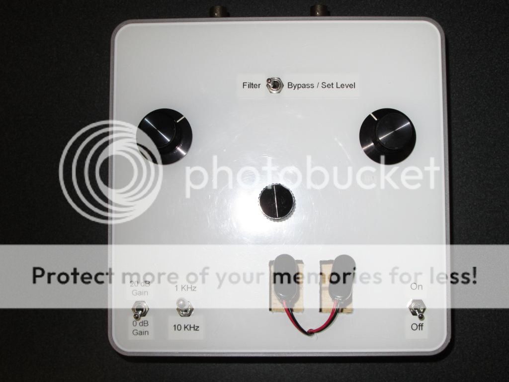
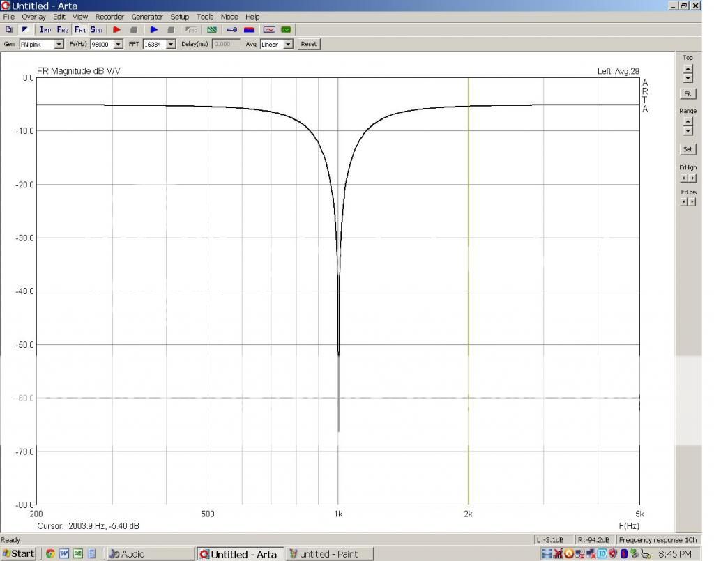
I built a version of the late Dick Moore's Twin-T notch and I use two ten turn precision pots as my adjustment to fine tune my notch. See photos and ARTA screen shot. I can tune using ARTA or one of my precision voltmeters in DB mode. I keep my oscillator centered at 1K and then adjust my notch filter. The smaller knob works in conjunction to sharpen the depth of the notch as you tune.


Looks like the 470r added to the 6k8 was fairly close to being "in Tune" with the oscillator output.
I am now having to accept that the only way to fine tune this notch to the fixed oscillator frequency is to accept rheostats in the three resistor legs.
Based on Simon's suggestion of big VR parallel to the small value to give ~470r, I have come up with a different layout using a dual pot for the two big Rs and a single track pot for the half value R. The two big VRs will introduce a matching error. I have a few very low value single pots (20r 50r 100r) that I can use in the centre to swing the two halves into closer matching.
But I only have dual log law vol pots in 10k and 100k values. The linear law pots I have are all single track.
At this stage I'll try the 100k dual log law and see if it's accurate enough to "tune in" the notch. If this goes reasonably, I'll order up a 100k linear for a rebuild later.
Last edited:
I would suggest all individual trim pots to minimize stray capacitance. It will also allow more precise trims.
I think you need somewhere around 478R. If you plot values, assuming that 430 is too small, 680 and 560 are too big, then you get a more linear curve by assuming that 470 is too small. Linear interpolation then gives 478.AndrewT said:So I need somewhere between 6800+560r and 6800+430r since I do not know which side of correct the 470r was.
Attachments
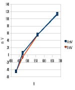
I did some calculations for an added resistor value + trim pot and came up with 510r in parallel with series combination of (100kVR + 5k1)I think you need somewhere around 478R. If you plot values, assuming that 430 is too small, 680 and 560 are too big, then you get a more linear curve by assuming that 470 is too small. Linear interpolation then gives 478.
That gave a range of 463r6 to 507r5
That funnily enough fits with your predicted 478r !!!!!
That's what I am going to try tomorrow. Between cinema and dancing, not enough time to assemble and test today.
I wish I could show you the Twin T layout with the adjustable resistor legs.I would suggest all individual trim pots to minimize stray capacitance. It will also allow more precise trims.
I think it neatly addresses the matching required.
I think you might be right about avoiding parasitic capacitances interfering with the notch performance.
I wonder if I could gang a pair of 100k Linear together with some cord, (old analogue tuner technology)?
I did some calculations for an added resistor value + trim pot and came up with 510r in parallel with series combination of (100kVR + 5k1)
That gave a range of 463r6 to 507r5
That funnily enough fits with your predicted 478r !!!!!
That's what I am going to try tomorrow. Between cinema and dancing, not enough time to assemble and test today.
There's a cute Java calculator somewhere, that spits out all possible series parallel combinations from 1% standard values in response to an unknown value and how close you want. I used it do an RIAA after measuring the caps on a bridge.
- Status
- Not open for further replies.
- Home
- Design & Build
- Equipment & Tools
- How do I tune my Twin T notch filter ?