
Getting a couple more sets up and running. No problems. I want to use your newer version but am to cheap to not use the boards and parts I have on hand especially when they work so well.
Thanks,
Evan
Thanks,
Evan
Attachments
Some amp control magic. ")
Starting up two 800VA and two 625VA trannies on a 10A circuit.
http://www.youtube.com/watch?v=H-X3QnwV8Eg
Starting up two 800VA and two 625VA trannies on a 10A circuit.
http://www.youtube.com/watch?v=H-X3QnwV8Eg
Last edited:
yngvejos, nice looking set up. What are the main speakers?
With these additional amps I will be fully active. Eight amps for the set up. I'm on a 20 amp dedicated circuit. The boards make staggering the start up easy. Being able to program without pulling the chip would be even better.
With these additional amps I will be fully active. Eight amps for the set up. I'm on a 20 amp dedicated circuit. The boards make staggering the start up easy. Being able to program without pulling the chip would be even better.
That's a lot for a 10A circuit.Some amp control magic.
Starting up two 800VA and two 625VA trannies on a 10A circuit.
http://www.youtube.com/watch?v=H-X3QnwV8Eg
total maximum operational power is 800+800+625+625 = 2850VA on a 220Vac supply that equates to 12.95Aac
But it does show how effective the staggered control start up strategy is.
yngvejos, nice looking set up. What are the main speakers?
With these additional amps I will be fully active. Eight amps for the set up. I'm on a 20 amp dedicated circuit. The boards make staggering the start up easy. Being able to program without pulling the chip would be even better.
I've got USB interface thoroughly tested and operating perfectly. Any new design boards will have onboard USB connections. On your older boards, a CP2102 USB to serial adapter can be connected to the FTDI header. They work great, and are dirt cheap.
CP2102 USB 2.0 to UART TTL 6PIN Module Serial Converter Free Cables | eBay
That's a lot for a 10A circuit.
total maximum operational power is 800+800+625+625 = 2850VA on a 220Vac supply that equates to 12.95Aac
But it does show how effective the staggered control start up strategy is.
It also shows how little power you actually use while listening to music. On the same circuit I have a second stereo with 800va trannie. I also run lightning, television, a fridge and various small things on the same circuit. I don't trip the 10 amp circuit breaker even when driving all amps close to clipping. Sine wave testing into dummy load would have been a different story.
Latest protection boards
Hi Jeff and other members,
I have the older 5-pair OPS and Spooky IPS boards ready, but didn't start them up yet. I need to build the protection system first to be sure what size of chassis I need.
I would like to build the latest and greatest protection version, but I'm not sure I have seen the complete set of boards and my knowledge is limited, so I need some help to identify the correct boards/schematics to do it.
If someone has leftover boards to sell with reasonable shipping cost to Bratislava/Europe I can buy them, or I can order the boards from China.
Could you please help to not get lost?
Thank you.
Stefan
Last edited:
Hi Jeff and other members,
I have the older 5-pair OPS and Spooky IPS boards ready, but didn't start them up yet. I need to build the protection system first to be sure what size of chassis I need.
I would like to build the latest and greatest protection version, but I'm not sure I have seen the complete set of boards and my knowledge is limited, so I need some help to identify the correct boards/schematics to do it.
If someone has leftover boards to sell with reasonable shipping cost to Bratislava/Europe I can buy them, or I can order the boards from China.
Could you please help to not get lost?
Thank you.
Stefan
I've got lots of boards. Are you using a single supply transformer or dual?
I've got lots of boards. Are you using a single supply transformer or dual?
Two 600VA 2x55V
Sent from my iPad using Tapatalk
I'll post some pictures and dimensions when I get to my computer.
thanks Jeff, please send also the cost of the boards. I hope the shipping from Canada is not more than the boards themselves [emoji851]
Sent from my iPad using Tapatalk
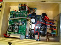
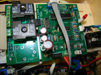
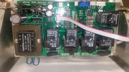
Here's the latest version of the board sets and some optional supplies with quick shut down rails. The main control board measures 170 x 100mm. All required fusing, relay, control transformer, ect is on board. You bring main power to it and connect your main supply transformers to it, eliminating all the extra clutter in the chassis.
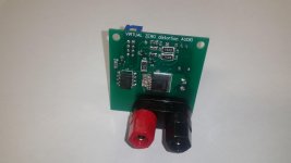
The control board connects some speaker relay boards which are designed to mount directly onto standard 19mm center speaker binding posts, but have footprints for optional Faston connectors for alternate output options. The speaker relays measure 51 x 54mm. There are small remote temperature sensor boards as well. They are slightly larger than a TO-220 transistor. They get bolted directly to the heatsinks.
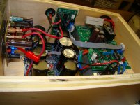
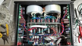
The optional power supply boards measure 100 x 100mm. There are two boards to each supply, giving you space for 8 35mm snap in caps. I've designed the whole supply/ control board package to mount on a single bracket that mounts to the bottom cover to make a compact easily serviceable power module. If you mount the transformers to the front cover of the amp, this all fits nicely in a 300mm deep 4U chassis. It fills the case up, but everything is accessible and can be removed completely from the amp in a couple minutes. The amplifier photo is of an earlier version of the control board, but gives you an idea of the finished outcome.
The whole control board set including speaker relay boards and temperature sensor boards is $34.90. The optional supply boards are $49.90 for two sets of boards. Shipping is $15 with a bubble mailer to anywhere in the world.
The control board connects some speaker relay boards which are designed to mount directly onto standard 19mm center speaker binding posts, but have footprints for optional Faston connectors for alternate output options. The speaker relays measure 51 x 54mm. There are small remote temperature sensor boards as well. They are slightly larger than a TO-220 transistor. They get bolted directly to the heatsinks.
The optional power supply boards measure 100 x 100mm. There are two boards to each supply, giving you space for 8 35mm snap in caps. I've designed the whole supply/ control board package to mount on a single bracket that mounts to the bottom cover to make a compact easily serviceable power module. If you mount the transformers to the front cover of the amp, this all fits nicely in a 300mm deep 4U chassis. It fills the case up, but everything is accessible and can be removed completely from the amp in a couple minutes. The amplifier photo is of an earlier version of the control board, but gives you an idea of the finished outcome.
The whole control board set including speaker relay boards and temperature sensor boards is $34.90. The optional supply boards are $49.90 for two sets of boards. Shipping is $15 with a bubble mailer to anywhere in the world.
Attachments
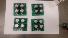
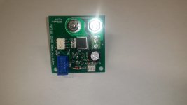
Here's the latest version of the board sets and some optional supplies with quick shut down rails. The main control board measures 170 x 100mm. All required fusing, relay, control transformer, ect is on board. You bring main power to it and connect your main supply transformers to it, eliminating all the extra clutter in the chassis.
The control board connects some speaker relay boards which are designed to mount directly onto standard 19mm center speaker binding posts, but have footprints for optional Faston connectors for alternate output options. The speaker relays measure 51 x 54mm. There are small remote temperature sensor boards as well. They are slightly larger than a TO-220 transistor. They get bolted directly to the heatsinks.
The optional power supply boards measure 100 x 100mm. There are two boards to each supply, giving you space for 8 35mm snap in caps. I've designed the whole supply/ control board package to mount on a single bracket that mounts to the bottom cover to make a compact easily serviceable power module. If you mount the transformers to the front cover of the amp, this all fits nicely in a 300mm deep 4U chassis. It fills the case up, but everything is accessible and can be removed completely from the amp in a couple minutes. The amplifier photo is of an earlier version of the control board, but gives you an idea of the finished outcome.
The whole control board set including speaker relay boards and temperature sensor boards is $34.90. The optional supply boards are $49.90 for two sets of boards. Shipping is $15 with a bubble mailer to anywhere in the world.
Well, this looks fantastic, I have to stare at it some more to get the idea. I will have some questions that could help others too and I will send a separate PM regarding the boards purchase.
Thanks a lot !
Jeff,
is it possible to make my own PSU boards to work with the control board? The reason is that I have 25 6,8mF capacitors, so I would like to use 6 capacitors per rail. Looking at your layout it could fit into a 5U chassis using the same method as you do. I think the PSU board schematic is not included in the PDF you sent ...
Your layout looks very good, but I'm not sure how to do the grounding properly. Do you have more pictures how it is done?
I never did SMD boards, but why not. I better try than run the amplifier without protection.
Thanks for helping the less experienced members.
- Home
- Amplifiers
- Solid State
- How to build a 21st century protection board