Hello,
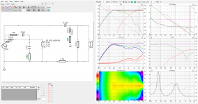
How to calculate the Q factor of the LPF and HPF component? I calculated the following component values

With the calculated component values the Q factor is around 0.5
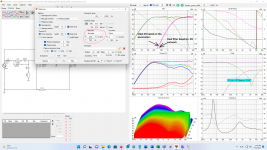
But for the flat frequency response I had to add two more resistors to the 2nd order LPF and HPF. How influences those resistors the Q factor. Resistors are marked green on the following picture

How to calculate the Q factor of the LPF and HPF component? I calculated the following component values
With the calculated component values the Q factor is around 0.5
But for the flat frequency response I had to add two more resistors to the 2nd order LPF and HPF. How influences those resistors the Q factor. Resistors are marked green on the following picture

The Q-factor for a Linkwitz-Riley filter is 0.5, as it is the equivalent of two Butterworth filters (Q=0.7071) in cascade. However, in order to find the Q-factor for your circuit, it maybe necessary to evaluate the actual transfer function, as the addition of resistors has caused the same to deviate from that of the LR filter. Besides, the HP and LP sections after the adjustment need not have the same Q-factor either.
Last edited:
The calculations take some time to do. However the resistors in this position alter the rolloff as well. You can get part way between first and second order, with a change in the level at the knee.
Thanks,
I want to understand why used Troels 15uF capacitor at the Discovery 12W design, and why my calculation shows 2.7uF. I'm 100% sure Troels design is good.
http://www.troelsgravesen.dk/Discovery-12W.htm
I want to understand why used Troels 15uF capacitor at the Discovery 12W design, and why my calculation shows 2.7uF. I'm 100% sure Troels design is good.
http://www.troelsgravesen.dk/Discovery-12W.htm
