You're missing the point.Not true. If the amplifier is commanding cone motion, higher damping factor will allow the cone to follow the signal more accurately.
If the damping does change (which of course shows the cone is moving in spite of the input signal).. and if the change is desirable, what is bad about it?
The point is that control of (or knowledge of) the amount of damping is reasonable, but a mandate for maximum damping (which will never be total due to voice coil resistance) doesn't make sense since it is situationally dependent.
Last edited:
I don't think I missed anything. That's okay.
Motion without a signal is bad. If the signal says stop, the cone should stop, not do it's own thing. The better the cone follows the signal, the more dynamic it will sound. Active systems always sound much better than passive crossover systems given the same components and proper setup.
Motion without a signal is bad. If the signal says stop, the cone should stop, not do it's own thing. The better the cone follows the signal, the more dynamic it will sound. Active systems always sound much better than passive crossover systems given the same components and proper setup.
If I understand you correctly, this would be to deny the existence of resonance. Resonance is not a bad thing in itself though it needs to be handled wisely.. and it must be handled since it cannot be avoided. A speaker system has a bandwidth and it has mechanical as well as electrical elements to it.Motion without a signal is bad.
I see no basis in fact for supporting this statement.The better the cone follows the signal, the more dynamic it will sound.
The case is uncommanded motion. If the cone doesn't follow the signal, that is distortion. Resonance is an impedance variation, you do want to control that. A speaker enclosure is, after all, a high pass filter. It's natural "Q" is designed with the interaction of the box and driver. Drive any speaker with a higher impedance and the response curve begins to follow the impedance curve. Do you want that? Probably not.
Don't confuse "over damped" as in the system design with the ability to control it. Two different things entirely. The term "damping factor" is an expression for an amplifier to control the load. Not resonance.
Don't confuse "over damped" as in the system design with the ability to control it. Two different things entirely. The term "damping factor" is an expression for an amplifier to control the load. Not resonance.
What you are calling distortion here, technically is a linear variation. It is nothing more than EQ, minimum phase in nature and quite harmless if it amounts to what we seek.
The effect is a simple voltage division between Rs and the speaker impedance. Using the word 'control' unqualified might give the impression something more is going on than actually is.is an expression for an amplifier to control the load.
With an ACTIVE speaker design where the drivers are connected directly to the amp, high amplifier DF is highly desirable >You're missing the point.
If the damping does change (which of course shows the cone is moving in spite of the input signal).. and if the change is desirable, what is bad about it?
The point is that control of (or knowledge of) the amount of damping is reasonable, but a mandate for maximum damping (which will never be total due to voice coil resistance) doesn't make sense since it is situationally dependent.
and the frequency response is sorted-out with active EQ. This is the concept of many highly acclaimed Studio Monitors.
A DSP and/or certain circuitry in the amplifier can "create" negative resistance, thus raising the damping factor, but this puts the system on the verge of oscillation. You probably don't want to do this. Using an amplifier with low output impedance and suitably large speaker cables does fine.I would like to have something that can increase (I already know how to decrease) the damping factor without adjusting the amplifier feedback, such as filtering, preamp, DSP algorithm, or similar... I have seen a DSP algorithm that can increase DP but don't have access to it. I would be grateful if someone could provide even a little information
But your request brings up questions: What are you trying to do? Why do you want to do this?
Decide what the response will be under the different damping factor, and use EQ or crossover to achieve it.
How about phase shifts? Addressing the frequency domain will not change the time domain?
How about stuff like back EMF?
I posted my thoughts on this elsewhere. It seems to me like the way to fix this is not to have any passive components between amp and speaker. So either go with a full bandwidth driver or do active crossover with multi amps. It goes right to the heart of the matter... control over the mass of the speaker ( stored energy ) should be the only thing the amp sees.... adding passive components is to add an energy transmission hysteresis into the circuit with distortions in the frequency and time domains.
Of course, you can also address this by going to a low mass ( panel ) or no mass ( Plasmatronics ) type of speaker.
Or get an active speaker.
Last edited:
I have a hypothesis about the rock slowing down. As it approaches the Heat Death of the Universe, it thinks "oh, why bother?"
Inverse EQ before the amp nulls these changes.How about phase shifts? Addressing the frequency domain will not change the time domain?
How about stuff like back EMF?
Hi,I would like to have something that can increase (I already know how to decrease) the damping factor without adjusting the amplifier feedback, such as filtering, preamp, DSP algorithm, or similar... I have seen a DSP algorithm that can increase DP but don't have access to it. I would be grateful if someone could provide even a little information
here some nuggets to help you find solution to your problem, what ever that is.
Damping factor is misnomer in sense that amplifier output impedance is just low impedance path for transducer to dampen itself with electrical damping, the backEMF, at main resonance. What the damping factor is it's just low impedance in series with a transducer, load for voltage generator the transducer is. Typically it's low impedance path through amplifier output and can be further manipulated with impedance network between amplifier and transducer.
If you have "high output impedance", low damping factor, transducer acoustic response changes basically for one reason: the transducer doesn't EQ itself as effectively anymore because it's not fully determining circuit current anymore. In this sense also saying that high damping factor amplifier is fully in control is false, because actually low output impedance amplifier has no control over current in circuit and in fact the load determines current, when only transducer hooked as load the transducer is fully in control of current and thus acoustic output. Current through voice coil is force in motor and means acoustic output, so only current amplifier with very low damping factor (high output impedance) would be fully in control of the transducer motion. Kinda, because if the transducer is not damped somehow, mechanically if not electrically to stop it resonating from any external excitation. Low impedance in series with the driver just prevents it from resonating itself due to any excitation.
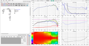
Here example of basic project that comes with VituixCAD. Changing amplifier output impedance here mainly affects woofer resonance, because of the impedance network between amplifier and transducer(s). Tweeter resonance doesn't peak, because it has impedance lowering shunt there.
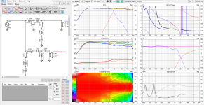
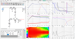
You could just add another shunt for woofer and the response looks somewhat original, it restores some electrical damping by reducing impedance in series with the driver. It also affects load of the amplifier so works as EQ as well.
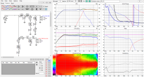
Obviously, you cannot lower impedance as low as with low amp output impedance, because the shunt is parallel with the driver as well. You could lower impedance of the shunt, and then counteract drooping lows by adjusting frequency response before amplifier. You could also restore the frequency response just with EQ before amplifier, without the shunt, but it would not increase electrical damping (lower impedance in series with driver) because it does not affect impedance in series with the driver. This you can do only by adjusting impedance in series with the driver.
So, damping factor is actually just low impedance in series with transducer so manipulate impedance in series with transducer by what ever means suitable in your case. That is enabling the transducer dampen it's own resonance with electrical damping. In addition to electrical damping you could dampen acoustically/mechanically by manipulating your box. If your frequency response is wonky after you are done, you could fix that independently with EQ before amplifier.
Last edited:
Well, exactly. Damping factor is defined as load impedance over the output impedance of the energy source. If you want the position of a speaker to accurately reflect the driving force, the impedance between it and the energy source (amplifier) must be as low as reasonably possible. That goes for starting and stopping motion at any instantaneous point in a waveform you present to the driver. This has limitations as the mass and velocity, plus compliance of the system comes into effect.
You can look at this from any viewpoint and play word games if you want. But, at the end of the day a speaker diaphragm will follow the signal more accurately with minimal resistance in that circuit. Yes, the driver has impedance that limits current flow, and it generates back EMF. You could think of it as when the driver is generating current, it is attempting to be the generator (not wanted) because it is moving on its own. That is what you want to damp out (control). Shorting (loading) this back EMF is what controls the driver. This is the major reason why active speaker systems with an amplifier connected directly to each driver sounds better. All other things held equal.
This has been shown empirically over many decades and is well understood. Now if you want to inject what sounds better to you, you've stepped outside the discussion and it is now a question of your personal preferences.
Words are important in sense that hopefully everyone understands the phenomenon well enough to be able to take advantage of it with their projects. For example, one could say that high output impedance sounds better and is known since the oldies, if the speaker connected to the amplifier is a single fullrange driver speaker which likely benefits from some bass and treble boost that results better sounding system, so everything is relative to what's in your hands and ability to tune the system to your benefit, what ever that is. Blanket statements don't cover all cases and I think it's more productive to understand what actually happens.
Far too often people on the forums attribute the damping to the amplifier, and how it controls the cone, which is kinda what happens but doesn't explain the phenomenon which is driver controlling itself. If one looks the math electrical damping only works with the main resonance, and higher up in frequency it doesn't. While damping the main resonance is half the victory one might have more win by increasing series impedance above resonance to low pass some motor distortion if it's a bad motor in high excursion wide bandwidth application. Not knowing this stuff could prevent somebody to actually take benefit of the phenomenon if they thought only amplifier matters.
Fun test for anybody who wants to experiment with significance of electrical damping:
Unhook a speaker from amplifier and drum the bass woofer with your hand, and it sounds much like a drum with "boom boom boom" type of sound as you drum it. Now, take a fork or anything conductive and short the speaker terminals with your other hand while continue drumming with the other and the sound changes to "thump thump" as you short the terminals, the driver dampens itself electrically, doesn't sound like a drum anymore. The fork has pretty good damping factor, it controls the cone well. Replace fork with a resistor to find out how much electrical damping matters with that particular box and driver. You can repeat the test by connecting the amplifier as well, hook one of the wires and touch other terminal with the other.
So, basically it's all about how a transducer works, and not much about how an amplifier works. You obviously know this stuff but a lot of readers don't as it's kind of counter intuitive after with the amplifier talk, so wanted to extend a bit.
Last edited:
I am very grateful to the experts who tried to answer my question.
Sure, can't get max DF, but I have low impedance speakers(1.6omh) and Faraday rings
The truth is I hate passive crossovers, wires, inductors, series resistors... so my amp is an active crossover, active speakers to optimize the wires...Not true. If the amplifier is commanding cone motion, higher damping factor will allow the cone to follow the signal more accurately. When the amp tells the cone to stop, it stops more quickly. Conditions are different under active drive.
The point is that control of (or knowledge of) the amount of damping is reasonable, but a mandate for maximum damping (which will never be total due to voice coil resistance) doesn't make sense since it is situationally dependent.
Sure, can't get max DF, but I have low impedance speakers(1.6omh) and Faraday rings
I'm looking for something that has a single punch of bass with little power, I hate rear rumble, and I'm driving a crazy commercial speaker (1.8omh, fs= 30hz, 10cm diameter, with a very short cone travel length)But your request brings up questions: What are you trying to do? Why do you want to do this?
Regarding the issue of self-oscillation of the amplifier circuit, I took a rather unusual step, which is to use an amplifier without negative feedback, so it will be difficult to oscillate.Hi,
here some nuggets to help you find solution to your problem, what ever that is.
Damping factor is misnomer in sense that amplifier output impedance is just low impedance path for transducer to dampen itself with electrical damping, the backEMF, at main resonance. What the damping factor is it's just low impedance in series with a transducer, load for voltage generator the transducer is. Typically it's low impedance path through amplifier output and can be further manipulated with impedance network between amplifier and transducer.
If you have "high output impedance", low damping factor, transducer acoustic response changes basically for one reason: the transducer doesn't EQ itself as effectively anymore because it's not fully determining circuit current anymore. In this sense also saying that high damping factor amplifier is fully in control is false, because actually low output impedance amplifier has no control over current in circuit and in fact the load determines current, when only transducer hooked as load the transducer is fully in control of current and thus acoustic output. Current through voice coil is force in motor and means acoustic output, so only current amplifier with very low damping factor (high output impedance) would be fully in control of the transducer motion. Kinda, because if the transducer is not damped somehow, mechanically if not electrically to stop it resonating from any external excitation. Low impedance in series with the driver just prevents it from resonating itself due to any excitation.
Here example of basic project that comes with VituixCAD. Changing amplifier output impedance here mainly affects woofer resonance, because of the impedance network between amplifier and transducer(s). Tweeter resonance doesn't peak, because it has impedance lowering shunt there.
View attachment 1452657View attachment 1452660
You could just add another shunt for woofer and the response looks somewhat original, it restores some electrical damping by reducing impedance in series with the driver. It also affects load of the amplifier so works as EQ as well.
View attachment 1452672
Obviously, you cannot lower impedance as low as with low amp output impedance, because the shunt is parallel with the driver as well. You could lower impedance of the shunt, and then counteract drooping lows by adjusting frequency response before amplifier. You could also restore the frequency response just with EQ before amplifier, without the shunt, but it would not increase electrical damping (lower impedance in series with driver) because it does not affect impedance in series with the driver. This you can do only by adjusting impedance in series with the driver.
So, damping factor is actually just low impedance in series with transducer so manipulate impedance in series with transducer by what ever means suitable in your case. That is enabling the transducer dampen it's own resonance with electrical damping. In addition to electrical damping you could dampen acoustically/mechanically by manipulating your box. If your frequency response is wonky after you are done, you could fix that independently with EQ before amplifier.
Huh yeah so the main problem is very low load impedance for amplifier. That's amplifier issue yeah 🙂
Meanwhile, if there is no suitable amplifier for such low load, and you cannot change the driver, you can try improve the sound by heavily damping the enclosure, which should reduce the resonance some. Also, make sure there is no peak in the response and EQ that out if there is, perhaps the damping is not such a huge problem.
If it's not enough, you could amuse yourself adding the shunt and then a series resistor to increase amplifier load, but if of course gets hot and loses sensitivity so it's a bad idea. But for sake of example this is how you could increase electrical damping some to reduce boom, without touching the amplifier.
Here I emulate situation, output impedance is similar to driver impedance so there is peak on the lows, the woofer resonates and sounds boomy.
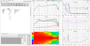
Adjust resistor in the notch filter down until boom reduces some. Use some series resistor to not have your amp oscillating. Here amplifier sees high impedance, and driver resonance sees "lower" impedance. If frequency response is now wrong, you could adjust that with your active xo.
Meanwhile, if there is no suitable amplifier for such low load, and you cannot change the driver, you can try improve the sound by heavily damping the enclosure, which should reduce the resonance some. Also, make sure there is no peak in the response and EQ that out if there is, perhaps the damping is not such a huge problem.
If it's not enough, you could amuse yourself adding the shunt and then a series resistor to increase amplifier load, but if of course gets hot and loses sensitivity so it's a bad idea. But for sake of example this is how you could increase electrical damping some to reduce boom, without touching the amplifier.
Here I emulate situation, output impedance is similar to driver impedance so there is peak on the lows, the woofer resonates and sounds boomy.

Adjust resistor in the notch filter down until boom reduces some. Use some series resistor to not have your amp oscillating. Here amplifier sees high impedance, and driver resonance sees "lower" impedance. If frequency response is now wrong, you could adjust that with your active xo.

Last edited:
Hi tmuikku,
A speaker system that sounds boomy has to do with speaker system "Q". When you get around unity, you have a hump in the response that becomes worse as the "Q" increases. Properly designed enclosures with the woofer they were designed for are not boomy. The same thing happens with ported or sealed systems.
Hi Hilumine,
Properly designed amplifiers shouldn't oscillate. Your load is very low impedance, but you should be able to design a high current output amplifier that doesn't oscillate. A no feedback design coupled with a low impedance load is simply a bad combination. You could look at a Stasis design, but they have higher output impedance due to the output transistors being outside the feedback loop.
A speaker cone has been described as operating in two modes depending on the frequency of the drive signal, mass controlled and compliance controlled. I highly recommend reading the book Current Driving of Loud Speaker, https://www.current-drive.info/ to see the only accurate full blown explanation of the physics that I'm aware of. I won't attempt to re-create what is in the book here.
The audio signal that is recorded represents the sound pressure to be produced at playback. To produce a pressure the speaker cone must accelerate proportional to the recorded signal. Many comments above miss
this fundamental concept.
To accomplish what the initial post hints at, changing the Q of the driver in the system, I use an active crossover and implement the Linkwitz Transform ( 2nd order asymmetric shelf filter) to modify the low frequency response to have whatever cut off frequency and Q that is desired for the design. The filter essentially cancels the natural response of the driver and compensates the system to produce the desired response. This works equally well with woofers, midranges and tweeters. With the midrange and tweeter I use it to produce part of the crossover high pass filter by raising the F3 up to the desired crossover frequency. If this is done with a resultant Q of 0.707 a second 2nd order high pass filter with Q = .707 can be cascaded to form a perfect 4th order Linkwitz - Riley high pass acoustic response from the driver.
https://en.wikipedia.org/wiki/Linkwitz–Riley_filter
The Linkwitz Transform:
https://www.linkwitzlab.com/filters.htm

This filter is available in several software programs such as WinISD, the Hypex Fusion filter design software for use with their multi-channel plate amps and miniDSP features it in their filter design excel spreadsheet on the first page labeled LT at the bottom of the screen. I attached this as a zip file.
The audio signal that is recorded represents the sound pressure to be produced at playback. To produce a pressure the speaker cone must accelerate proportional to the recorded signal. Many comments above miss
this fundamental concept.
To accomplish what the initial post hints at, changing the Q of the driver in the system, I use an active crossover and implement the Linkwitz Transform ( 2nd order asymmetric shelf filter) to modify the low frequency response to have whatever cut off frequency and Q that is desired for the design. The filter essentially cancels the natural response of the driver and compensates the system to produce the desired response. This works equally well with woofers, midranges and tweeters. With the midrange and tweeter I use it to produce part of the crossover high pass filter by raising the F3 up to the desired crossover frequency. If this is done with a resultant Q of 0.707 a second 2nd order high pass filter with Q = .707 can be cascaded to form a perfect 4th order Linkwitz - Riley high pass acoustic response from the driver.
https://en.wikipedia.org/wiki/Linkwitz–Riley_filter
The Linkwitz Transform:
https://www.linkwitzlab.com/filters.htm
9 - 12 dB/oct highpass equalization ("Linkwitz Transform", Biquad)
This filter is available in several software programs such as WinISD, the Hypex Fusion filter design software for use with their multi-channel plate amps and miniDSP features it in their filter design excel spreadsheet on the first page labeled LT at the bottom of the screen. I attached this as a zip file.
Attachments
Last edited:
- Home
- General Interest
- Everything Else
- How to get high damping without amplifier feedback interference