Well, the problem is that a 10k resistor with 10mA going through it would need to drop 100V, and the B+ to that LTP stage is only +345V. That leaves only 245V for both the triodes and their plate and cathode resistors. Since 6GU7 has internal plate impedance of 5500 ohms or so, the plate load resistors need to be about 12k minimum. The bias needs to be in the -9V area to get enough swing for driving the 6B4G's to full power. So that's 72V dropped across the plate load, 9V dropped across the cathode resistor, leaving a plate voltage for the tube of only +165V. That means the bias will be down around -6V. 6V peak input times gain of about 8 equals only about 48V peak output. We need 60V peak, at least.
It now looks like the tube type will need to be changed to something with much higher mu, which means higher internal plate impedance. That doesn't usually work so well driving big power triodes with their high-ish input capacitance. Of course the way around that is to add MOSFET followers, but then the amp is no longer very simple...
So, my feeling is that either a negative supply has to be added for the LTP stage, or the whole thing should be changed over to something more Williamson-like (e.g., the Einstein amp). So in the end, for this particular case...
I like the Williamson-Einstein idea too. 😀
--
I agree with your analysis, had the ECC88 in mind when stating the operating points. I should have said that.
PS for the OP. I m afraid the nuance is drowned in the hum. Hum does not have to be audible at the listening position to disturb things.
That would be just barely enough, correct?
yes, but for a non-global negative feedback type amp, that will work,
if that was the design goal....
I'm following the thread closely, but I think you guys havent finished discussing all the option I have for the amp and I really cant be of any help as I dont understand half your talking about!
Ajt, the goal is to have the best sound possible without having to replace the opt and mains and keep the 6b4g tubes. Go with a perfectly well working design that gets the best out of what I already have... Budget is around 200$ maximum for this project.
So far, I think everyone agree to:
replace the LM317 with a 750R 1W resistor.
change for ECC88
OK, I think it's time to put a mid-thread summary together...
From what I can see, the goals are:
1) Best sound possible (We need to know exactly what that means...)
2) Use the power transformers and OPT's that are in there now.
3) Use 6B4G output tubes.
4) Budget is around $200 USD.
I agree with costis_n that the "Einstein" amp is the way to go. Why?
- It's still a very simple design.
- No need for a negative supply, because no need for constant current source.
- Uses the 6B4G and 6GU7 tubes you already have.
- Can use the power xfmr and OPT you already have.
- Won't require major surgery to the chassis.
- Has plenty of gain for adding negative feedback, but with one (major) caveat -- you won't be able to use more than 6 to 10 dB of NFB. Any more and instabilities, oscillations or ringing are likely. That's not such a big deal with 6B4G's, though. That's a pretty linear output tube.
__________________________________________
I believe that if you take out the constant current sink in the tail of the 2nd stage (LTP) 6GU7-pair and replace it with a 750R resistor, push-pull balance will be poor. Even worse than with the LM317 as the current sink. That's why I keep thinking that the first 6GU7-pair should do the phase splitting, with the second 6GU7-pair used as a push-pull driver. If you look at the two circuits I pulled off the web and posted in post 58, you'll see that they both do exactly that, but in different ways. The last step would be how to implement that within the constraints of youknowyou's list of desired features.
Which brings me back to the "Einstein" amp circuit. All that needs to be done is reduce the B+ enough to keep from burning up those lovely 6B4G's, and adjust the parts values to work for 6GU7's instead of 6SN7's. No need for any additional power supplies or current sinks.
Is there a better solution?
--
Thanks for weighing in. Sounds like another vote for switching to EL34 outputs, right? Half the drive requirement means another 3dB of NFB possible, for a total of -6dB. That would be just barely enough, correct? (Still not optimal, I know...)i think not enough open loop gain for feedback.
6gu7 has mu of about 17, the output tubes are triodes...
yes, but for a non-global negative feedback type amp, that will work,
if that was the design goal....
Ajt, the goal is to have the best sound possible without having to replace the opt and mains and keep the 6b4g tubes. Go with a perfectly well working design that gets the best out of what I already have... Budget is around 200$ maximum for this project.
From what I can see, the goals are:
1) Best sound possible (We need to know exactly what that means...)
2) Use the power transformers and OPT's that are in there now.
3) Use 6B4G output tubes.
4) Budget is around $200 USD.
I agree with costis_n that the "Einstein" amp is the way to go. Why?
- It's still a very simple design.
- No need for a negative supply, because no need for constant current source.
- Uses the 6B4G and 6GU7 tubes you already have.
- Can use the power xfmr and OPT you already have.
- Won't require major surgery to the chassis.
- Has plenty of gain for adding negative feedback, but with one (major) caveat -- you won't be able to use more than 6 to 10 dB of NFB. Any more and instabilities, oscillations or ringing are likely. That's not such a big deal with 6B4G's, though. That's a pretty linear output tube.
__________________________________________
I believe that if you take out the constant current sink in the tail of the 2nd stage (LTP) 6GU7-pair and replace it with a 750R resistor, push-pull balance will be poor. Even worse than with the LM317 as the current sink. That's why I keep thinking that the first 6GU7-pair should do the phase splitting, with the second 6GU7-pair used as a push-pull driver. If you look at the two circuits I pulled off the web and posted in post 58, you'll see that they both do exactly that, but in different ways. The last step would be how to implement that within the constraints of youknowyou's list of desired features.
Which brings me back to the "Einstein" amp circuit. All that needs to be done is reduce the B+ enough to keep from burning up those lovely 6B4G's, and adjust the parts values to work for 6GU7's instead of 6SN7's. No need for any additional power supplies or current sinks.
Is there a better solution?
--
Last edited:
While we're on the subject of defining design goals...
youknowyou, what size is the listening room where these amps will be used? Is it a large room? How loud do you play music in this system?
A good way to answer that last question with some precision is to use member Pano's little test in the thread A Test. How much Voltage (power) do your speakers need?
That will tell you whether or not this PP 6B4G will deliver the power you need for the music you play and the way you listen to it, in the room where you'll be listening. Highly recommended.
I did that test and was surprised to find that I only really need 10 watts per channel. 15Wpc would be better. Too bad I only have 6Wpc from my 2A3's. (I don't listen very loud, and my living room is on the cozy side.)
--
its in a living room quite small, like 11x14 feet.
since I will use a 92 db/W de capo 3 a mm speakers, I doubt I need a lot of power seriously.
I never listen over 100 db, and my listening average is 75 db. I very rarely listen over 85 db to be honest.
since I will use a 92 db/W de capo 3 a mm speakers, I doubt I need a lot of power seriously.
I never listen over 100 db, and my listening average is 75 db. I very rarely listen over 85 db to be honest.
i like designs that do not have too many voltage gain stages...
a power triode output need not use global negative feedback...
having said these, a pentode ltp input driving the triode outputs is what i would go for...
a power triode output need not use global negative feedback...
having said these, a pentode ltp input driving the triode outputs is what i would go for...
How far from the speakers are you when you listen? 3 feet (1 meter)?
Let's say you sit 3 feet from one speaker, and that you're listening to one speaker (just as an example).
Your speaker needs 1 watt input to output 92dB SPL (that might be optimistic, but let's go with it).
That means the speaker needs 2W for 95dB SPL, 4W for 98dB, and 8W for 101dB. That's as loud as you're going to get from a pair of 6B4G's, and I hasten to add that these are very optimistic numbers.
Since you'll be listening in stereo, you can add 3dB to all those numbers. So to get 101dB from the two amps and speakers, you'll need 4W per channel. So yes, it's all working out in your favor. PP 6B4G's should do ya.
--
i like designs that do not have too many voltage gain stages...
Yes, me too. But this is a special case. The design has to use the parts at hand, and be simple to construct, with a good chance of success.
a power triode output need not use global negative feedback...
Well, with these particular OPT's (Dyna A470), I've never had great luck without NFB around them. I don't think it's the output tubes that need the NFB, I think it's the OPT's. And one of the design goals is to use those OPT's. But yes, agreed. PP 6B4G's are likely to sound nice without NFB, even with these OPT's. Not "ultra-fi," but nice.
having said these, a pentode ltp input driving the triode outputs is what i would go for...
Wait... a pentode LTP? But the output impedance from pentodes would be very high, and the input (Miller) capacitance of those output triodes is fairly high. You'd need NFB to bring the high frequency response back up from the dead, wouldn't you? Unless you added MOSFET (or cathode) followers after the pentode LTP plates, which is a very interesting idea. But now we're getting complicated again...
--
running the pentodes with high plate currents(bigger tail currents) can be done...
one example.....DCPP Amp
another....Garry Pim's Tabor amp...http://www.pimmlabs.com/web/1624.gif
one example.....DCPP Amp
another....Garry Pim's Tabor amp...http://www.pimmlabs.com/web/1624.gif
Yes, but they're both driving pentode output stages. Not even ultralinear. No worries about driving the input capacitance of the output tubes if they're pentodes. Wouldn't that be more difficult driving big triodes like 2A3 or 6B4G?
IT transformers are a no-go with this budget....
I like the Einstein idea more. And it does not have fb.
I wound not recommend a feedback construction to anybody who does not have a scope. These designs, unless you use a known 100 % design and transformer need tweaking in the comp networks.
And yes, you can adjust for any decent transformer, but you need a signal gen and a scope.
on the road
I was just looking at the 2A3 data sheet (RCA). It shows the conditions for push-pull class AB1:
Va = 300V (a-k, max)
Ia = 40mA (per tube)
Vg = -62.5V
Rk = 780R (one resistor for both tubes)
Rload = 5000 ohms (anode to anode)
Since we're using a 4300 ohms a-a primary, the tubes will draw more current. Changing the cathode resistor to 750 ohms (up from the 500 ohms that's in there) will bring the anode current more into line with specified limits. Even if the current only drops to 50mA per tube, that would be OK (300V on the plate times .05A plate current = 15W plate dissipation, which is the specified maximum).
So, the first change I'd suggest is for reliability and longer life for those nice 6B4G's. Change the 6B4G's cathode resistor to 750R. That resistor should be rated for a minimum 15W.
Even if you change nothing else, that should be done.
--
Yes, but they're both driving pentode output stages. Not even ultralinear. No worries about driving the input capacitance of the output tubes if they're pentodes. Wouldn't that be more difficult driving big triodes like 2A3 or 6B4G?
agreed, but that doesn't mean it can not be done, it is a matter of getting the driver voltage swing and the currents right....
i think that this is today's challenge to designers, design decisions taken years
ago when capacitors were not that improved compared with today's offerings,
i believe we should not be limited by what was done in the olden days of tubes...
to me as long as you respect the plate dissipation ratings of each tube, then
you can run them as you like....
the real problem is a too emphasized bass and not enough details.
1. you may try removing the 10ufd/600volt cap at cathode of the tube rectifier.....
2. replace coupling caps to output grids from 0.22 to 0.1 or even 0.05, same with the first stage..
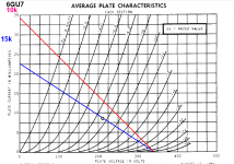
3. replace the 15k/5watt plate load resistors of the ltp to 10k for more swing...
AJT, I'm trying to understand what your suggestion #3 will accomplish. I've plotted loadlines for 6GU7 with 15k plate load resistor in blue, and 10k plate load resistor in red. B+ is 340V in both cases. I don't see much difference in voltage swing, but I could be reading the loadlines incorrectly. I do see that the 10k loadline is more vertical, which increases distortion and plate dissipation quite a bit.
6GU7's plate impedance at Va = 210V and Vi = 8mA is about 6k ohms. A 10k plate resistor would be a load of less than 2(ra). That's on the edge.
__________________________________________________________
I'm intrigued by the idea of using a pair of pentodes in push-pull to drive the 6B4G push-pull pair.
Assuming the input capacitance of a 6B4G is about 75pF each, including strays, that means if we want a worst-case F3 of 50kHz, the preceding driver stage's output resistance would have to be 43k ohms. If we shoot for an F3 of 200kHz (a decade higher than 20kHz, which is the lowest frequency of interest) then the driver stage output R needs to be 11kHz.
The internal plate resistance for D3a is listed as 120k ohms. (That would equate to an F3 of 18kHz driving the grid of a 6B4G.)
Also, since we're RC-coupling the driver stage to the output stage, we need to consider the load presented by the output stage's grid leak resistors. 6B4G with cathode bias max value grid leak resistor is 470k ohms. You want the output stage grid leak R to be 10x the driver stage Rout. I think 330k ohms is as high as I'd want to go for 6B4G grid leak resistors. That means the driver stage Rout can't be any higher than 33k in this amp.
6GU7 ra || 15k Ra is about 4k7 ohms. That works fine, even with 47k ohm grid leak resistors on the 6B4G's.
Since a pentode's output R (open loop) is going to be at least 30k ohms, and most likely much higher, how would we get a decent bandwidth on the high frequency end of the audio band with a pentode LTP driving 6B4G's?
--
[youknowyou: Try changing R15 and R16 from 300k to 100k. That will filter out very low frequencies going into the output stage, which should help with the problematic bass boost.The 220k ohm after the first stage should stay. It can't be made much lower in value without loading down the first 6GU7.
Don't forget to change the 6B4G cathode resistor to 750R (must be rated minimum 15W).]
--
Attachments
Last edited:
my listening position is around 2 meter away from the speakers and I tend to stay at the same place when I listen in the sweet spot.How far from the speakers are you when you listen? 3 feet (1 meter)?
Let's say you sit 3 feet from one speaker, and that you're listening to one speaker (just as an example).
Your speaker needs 1 watt input to output 92dB SPL (that might be optimistic, but let's go with it).
That means the speaker needs 2W for 95dB SPL, 4W for 98dB, and 8W for 101dB. That's as loud as you're going to get from a pair of 6B4G's, and I hasten to add that these are very optimistic numbers.
Since you'll be listening in stereo, you can add 3dB to all those numbers. So to get 101dB from the two amps and speakers, you'll need 4W per channel. So yes, it's all working out in your favor. PP 6B4G's should do ya.
--
Yes, we have a scope and gen.IT transformers are a no-go with this budget....
I like the Einstein idea more. And it does not have fb.
I wound not recommend a feedback construction to anybody who does not have a scope. These designs, unless you use a known 100 % design and transformer need tweaking in the comp networks.
And yes, you can adjust for any decent transformer, but you need a signal gen and a scope.
on the road
Ive been recommended to use negative feedback with those opt so if Its doable, I would like to do this if it makes sense from you guys
Quoting yourself is bad form, but AJT, I have a question about pentode operation...
If we take a D3a as our example, what happens if we use it with a 15k plate resistor, and a +100V screen supply? If the D3a internal plate impedance (ra) is 120k, do we figure output impedance by ra in parallel with Ra (plate load resistor)?
If yes, then we get an output impedance of only 13k from the D3a pentode, which will work. But... would a D3a run that way swing enough volts out? Its amplification factor for g1-g2 is listed as 80. But what is its amplification factor from the plate? (I have a lot to learn about pentodes.)
--
myself said:Assuming the input capacitance of a 6B4G is about 75pF each, including strays, that means if we want a worst-case F3 of 50kHz, the preceding driver stage's output resistance would have to be 43k ohms. If we shoot for an F3 of 200kHz (a decade higher than 20kHz, which is the lowest frequency of interest) then the driver stage output R needs to be 11kHz.
If we take a D3a as our example, what happens if we use it with a 15k plate resistor, and a +100V screen supply? If the D3a internal plate impedance (ra) is 120k, do we figure output impedance by ra in parallel with Ra (plate load resistor)?
If yes, then we get an output impedance of only 13k from the D3a pentode, which will work. But... would a D3a run that way swing enough volts out? Its amplification factor for g1-g2 is listed as 80. But what is its amplification factor from the plate? (I have a lot to learn about pentodes.)
--
Last edited:
Yes, we have a scope and gen.
Ive been recommended to use negative feedback with those opt so if Its doable, I would like to do this if it makes sense from you guys
The first step is to design the amp so that it is as linear as you can get it without feedback ("open loop"). Then you add feedback, if desired.
--
- Status
- Not open for further replies.
- Home
- Amplifiers
- Tubes / Valves
- How to improve this 6B4G push-pull circuit