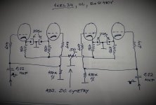
I`m in middle of asembling two 70W monoblocks working in A1 class(up to 100W in AB1 class) , PP-UL-OPS is with 4xEL34 using automatic bias , cathodes bias network consist from four 470R/9W wire wound resistors , four 220uF/63V electrolytic cond. , and one 50R/10W wire wound trim pot to precise adjust DC balance , since IMO for best amp performance it is important to have around zero mA disbalance inside of OPT primary coil,
btw , one mas produced Iskra HI-FI amp from the late 70` use hybrid bias configuration , I have couple of them and I can say that those amps sound just great .
btw , one mas produced Iskra HI-FI amp from the late 70` use hybrid bias configuration , I have couple of them and I can say that those amps sound just great .
Attachments
Last edited:

I build relatively small amplifiers, that are mostly PP pentode and rarely over 10WPC. I have found the TL431 to be most useful in creating a hybrid bias scheme for the output tubes. What drove me in this direction was the article Sy wrote about the RLD years ago. The TL431 circuit seems to accomplish the same thing as the LEDs in the RLD, except without the LEDs. With this circuit there is no need for a bypass cap, which I think is a good thing. The circuit is best described by member Artosalo here.
Hello!
I have a question. We discuss very often the pros and cons of fixed vs self-bias for output stages. But I do not see often hybrid bias, where self-bias and fixed bias are combined, into something like this:
View attachment 1273976
What are the drawbacks of this approach? I can understand that it is a bit more complex, even when the current source is replaced by a resistor. But I can see a big advantage, which is reducing the power dissipation of the bias component, while still retaining some of the self-bias advantages. Using a CCS instead of the bias resistor makes it even better.
I'm sure it is used somewhere, but not very often. Any ideas?
Regards,
Jose
You are on the right track.
The idea is to keep a constant DC bias current flowing from Anode to Cathode. Now if an Anode load resistor is used the constant current flowing through this load resistor fixes the Anode bias voltage. So you have a fixed Anode to Cathode current and a fixed Anode DC bias voltage. The advantage of this is fixing two axes of the characteristic curves for this triode at a good place (most linear). For AC signals then of course the current from Anode to Cathode and the Anode voltage are varying.
For this circuit using half of a 5670 triode V1A using a Anode to Cathode current of 8mA and with the resistors shown the Anode sits at about 130V, gain is about x3.
Anode voltage vs current for different grid voltages for the 5670 valve.
At steady state the power dissipated in the valve due to this bias is approximately 8mA x 130V, about 1Watt. In this example the Grid DC level pin 3 is 0V zero volts, the Cathode pin 2 stays at about between +1 and +2 volts. So the Grid bias is negative of the Cathode as it needs to be. The V-15 supply is needed to give the current generator enough headroom. The 1K5 Cathode resistor provides negative feedback helping to keep distortion low. At the gain of approximately x3 the THD can be as good as -60bB for this circuit assuming a 1 volt peak input signal. The Grid input impedance can of course be very high.
Disadvantages - complexity maybe. Hope that helps your thinking.
Last edited:
With regard to the "sweet spot" this kind of bias is aiming at, I tried plotting the same graph adding a load line for the 6K Anode resistor shown, here is that graph:

To my way of thinking the middle useful part of this load line is in the most linear part of the characteristic curve and is held there by the constant current bias.
To my way of thinking the middle useful part of this load line is in the most linear part of the characteristic curve and is held there by the constant current bias.