Following the instructions located here A Complete Guide to Design and Build a Hi-Fi LM3886 Amplifier - Circuit Basics
I have the thing built and am testing it with a 1kHz sine wave as input. I am not using the toroid xformer for power yet, I am using my desktop DC power supply. It can furnish +20, -20, and 0 volts. I have taken pictures of the oscope at various points and was trying to figure out why I am not getting and sound at the speaker. Additionally, I do not know where to connect the wire to the --neg of the speaker according to. I cant figure out where that V- wave came from ? Thats straight from the bench power supply.
The schematic. The input sine wave., The output wave, The V- Reading
Attachments
I do not know where to connect the wire to the --neg of the speaker according to.
To the power ground.
I suspect the missing dot's quite deliberate - to keep the two GNDs separate on the PCB and have them linked at some external star point. Good practice with classAB chipamps as the PWR_GND is contaminated with non-linear currents via the supply decouplers.
The negative supply voltage is too low to unmute the LM3886. D1 and R5 are preventing the required current flow that is needed. Try a bridge over D1.
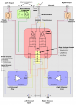
Signal GND needs to connect to Power GND for the amp to work.
Speaker GND connects to all the grounds. To get the best results, each GND connection should be made in a specific order. Here is a good layout.
Also, if you are using C13/R8 you should place a 220pF capacitor between inputs (pin 9-10). See the datasheet schematic.
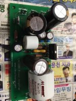
It would be helpful if you posted a photo of your build. It is really easy to make amps behave badly.
Last edited:
The power supply for this project has connectors for all the grounds that you mentioned. I wanted to test each amp independently so as to get part of it correct. As I recall all the gnd are connected together. 1 thing that I might have wrong is that I am connecting the center pole of the mains to the earth connector on th power supply. And that seems to be connected to all the other gnd. The problem is that I have blown up quite a few components. I will see if I can find the wiring diagram that shows that.
Thanks a lot for the help
I
Thanks a lot for the help
I
Very strange
When I 1st turn the power on, I hear the 1khz coming out of the speaker.
Then it slowly fades to silence.
What the heck could be causing this ????
When I 1st turn the power on, I hear the 1khz coming out of the speaker.
Then it slowly fades to silence.
What the heck could be causing this ????
I just discovered that the V- is slowly dropping down. It starts at 25- and works down to -9. V+ is at 53.
This is from my desktop supply. Let me try it with the proper xformer.
This is from my desktop supply. Let me try it with the proper xformer.
Post a photo of your test setup with PSU connected. You do have a heatsink fastened to the chip?
Last edited:
- Status
- Not open for further replies.
- Home
- Amplifiers
- Chip Amps
- I am building the Circuit Basics LM3886 amplifier.


