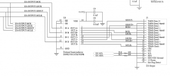
Hi everyone. As many of you probably know, PS Audio is one of the manufacturers out there supporting I2S digital output/input format as a better alternative to S/PDIF.
The I2S format has separate clocks and data and lower jitter and better performance if handled properly. I2S is the native format inside every CD player. If you are using a separate transport, the native I2S inside the transport must be converted into S/PDIF format to get out and into your DAC. This is not the best way to do this.
When we released the PerfectWave DAC and Transport a year ago, we decided to include I2S as a standard interface between the two machines. We also decided that the best way to transfer the I2S data was over an HDMI cable. There are many great HDMI cables available on the market and it's an excellent interface cable.
Our engineering department spent a great deal of time developing a "standard" that works quite well and several other companies have already adopted this standard. Our hope is that more and more manufacturers will include a similar interface on their devices.
I figured the DIY guys would be the logical choice to get this ball rolling so I have attached the schematic for the interface. You are free to use this in any way you see fit. I would appreciate a bit of publicity on this, but nothing more.
If you have questions, direct them to me paul@psaudio.com and I'll do my best to pry someone out of engineering to help.
Good luck and have fun. Drop me a note if you do this. The results are noticeably better than running through S/PDIF or AES/EBU.
Paul
Attachments
That's nice, but it wold be more usefull if it had capability for surround sound too.
IMO the clocks should be combined in just one, there is no need to dedicate 3 separate differential channels for that. Other than simplify the schematics that is...
I would use the 'Clock' pair for general clock and the 'Data' pairs for the 3 audio data necessary for 5.1 surround.
IMO the clocks should be combined in just one, there is no need to dedicate 3 separate differential channels for that. Other than simplify the schematics that is...
I would use the 'Clock' pair for general clock and the 'Data' pairs for the 3 audio data necessary for 5.1 surround.
The I2S bus needs all four of those signal pairs. The MCLK is 256X the sample rate, The LRCLK tells you left or right channel 1X sample rate, and the bit clock is 64X the sample rate.
That one could possibly be derived from the MCLK. So, you would still need a minimum of three.
It would be better to add another HDMI cable for multichannel.
That one could possibly be derived from the MCLK. So, you would still need a minimum of three.
It would be better to add another HDMI cable for multichannel.
You need just the bit clock, the rest can be derived (XTAL clocks, triggered by BCLK in the other end for MCLK), eventually with some encoding for the LRCLK in the stream...
There are only 4 pairs in a HDMI or in a CAT5E cable. If some could work around the three clock issues... that would be awesome.
But not on the RIAA "guidelines" I guess.
There are only 4 pairs in a HDMI or in a CAT5E cable. If some could work around the three clock issues... that would be awesome.
But not on the RIAA "guidelines" I guess.
Last edited:
... that would be awesome.
But not on the RIAA "guidelines" I guess.
😀
now you're designing a new interface that's not I2S format
😀
if each sample has 24 bits of data, then you do have 8 trailing bits available in each word that could identify the channel. and a few other parameters.
No, I was thinking in leaving the data untouched, but encoding differently the clock.
Something easy to do at DYI level like voltage level shifting for L/R channels. After all is a low freq clock.
MCLK I guess is easy to accurate regenerate from bit clock? PLL maybe?
Hmmm, sorry, didn't want to hijack this thread. I'll think about it in a month, now I take some exams 🙁
Something easy to do at DYI level like voltage level shifting for L/R channels. After all is a low freq clock.
MCLK I guess is easy to accurate regenerate from bit clock? PLL maybe?
Hmmm, sorry, didn't want to hijack this thread. I'll think about it in a month, now I take some exams 🙁
I'd be careful of this approach. PLL's introduce jitter and are not desirable if you can avoid it. What we have shown here works extremely well.😱
You are right about jitter, but... MCLK is not that important for jitter. Actually only Delta-Sigma DAC's require that, the R-2R type generate their MCLK own clock with a capacitor.
Nice of you guys to share....!
jk
Thanks from me too. A question, do you not use resistors in the balanced output lines to limit power supply noise at the driver?
Dan
Thank you for posting this, I have a project in mind that will require I2S output and this looks like a good solution. My plan was to do something similar, but if I can interoperate with other equipment and help an ad-hoc standard emerge, all the better. Your design is pretty DIY-friendly too, that transmitter is available in SOIC even.
I assume you are using the DS90LV032A as receiver too with success?
I too am curious what you're using the I2C lines for.
I assume you are using the DS90LV032A as receiver too with success?
I too am curious what you're using the I2C lines for.
The LVDS lines used in HDMI are very fast, orders of magnitude faster than required for this application. You could easily mux the 3 streams on the same data line, triple the bit clock and demux at the receiver (muxing 4 streams might actually be a bit simpler), leaving the critical clocks alone. Probably the easiest way to do it too. But yeah, then you're not using this 'standard' I2S interface anymore, and complexity is increased. This is nice and simple.No, I was thinking in leaving the data untouched, but encoding differently the clock.
Last edited:
Interesting. We have been doing nearly the same thing here - I²S via LVDS. But we went for a much cheaper wiring system - standard RJ45 and CAT6 cabling.
LVDS signalling is not normally associated with particularly low jitter anyway, so you would probably want to lock a rock to mclock anyway, if minimal jitter is your thing.
National Semi app note: www.national.com/an/AN/AN-977.pdf gives some numbers (at much higher data rates, but you can extrapolate to around 1ns of added pk/pk jitter for the link (Given some audio types seem to think that 10ps is the threshold (really not convinced), then a whole nanosecond is not that impressive).
I would also note that LVDS is only good for around a volt of common mode, rather unimpressive for a link intended to run between cases where one may be class I and the other class II insulated.....
As a low speed consumer interface the cables may be OK, but I would favour RS485 with suitably controlled slew rate drivers (Much more robust).
Mclock can indeed be regenerated from bit clock, and indeed both the mclock and bitclock can be produced from the LRclock (LRclock is timing wise what the studio guys call wordclock).
Now personally I have never seen PLLs as a bad thing, make the loop corner frequency low enough and the phase noise becomes dominated by the quality of the local oscillator. Make the LO something sort of like a Driscoll design (cannot use directly it is third overtone, but something similar is not hard), with good RF layout and the external word clock quality will have almost no impact on the jitter at the output.
Sure you can screw up a PLL design, but you can screw up anything!
Regards, Dan.
I have a digital usb converter with an output called IIS RJ45 and a DAC with I2S HDMI input. The converter works on 4 pairs of MCLK/GND, LRCK/GND, DATA/GND nad SCLK/GND. I suppose according to the attached PS Audio scheme that MCLK/GND go for pins 10/12 (hdmi), LRCK/GND pins 9/7, DATA/GND 16/?, 15/?. Does any one if it's possible to make it work?
Ok, so I don't quite get the purpose of this thread.
All I have got out of it so far is that you can use a DS90LV031A driver to send the i2s data down an HDMI connector and cable to a DS90LV048A ( or equivalent) receiver.
So is that it?
Or is there an insinuation that we can make a HDMI to i2s converter using some available chip?
The HDMI receiver chips that I have seen are HDMI to i2s converter chips also with video output pins.
I was also under the impression that the HDMI receiver chips were unobtainable for the regular DIYer as they are only sold to manufacturers.
So, again, what is this thread about?
Is it about making a balanced i2s transmitter/receiver or about making a HDMI to i2s converter?
If the latter, can someone advise where DIYers can buy some HDMI receiver chips to play with?
Thank you
The 1st post pretty much covers the reasons. If you are satisfied with SPDIF then it is a moot point. It's for Audiophools like me that will never be satisfied.
The 1st post pretty much covers the reasons. If you are satisfied with SPDIF then it is a moot point. It's for Audiophools like me that will never be satisfied.
I'm already running i2s to my DAC.🙂 SPDIF is not quite as good as i2s.
I just didn't get why the "schematic" was posted. The "schematic" was actually a bum steer. There is nothing new or revolutionary about balanced line drivers.
The whole post just seems to be an advertisement for a product in the wrong section of the forum under the guise of something DIY. There is no advise on track layout or power supplies or anything useful at all to do with the actual practical implementation of i2s over HDMI cable.
The author of the first post may as well just written "hey guys, use a balanced line driver for i2s......."
Last edited:
- Status
- Not open for further replies.
- Home
- Source & Line
- Digital Line Level
- I2S standards from PS Audio