I'm in.
Do you think the noise comes from the pi and fifopi?
Might an above dac shield with Joe's filter not been an option too?
Do you think the noise comes from the pi and fifopi?
Might an above dac shield with Joe's filter not been an option too?
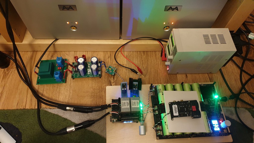
It keeps getting bigger. Just messing about with different psu arrangements for the DAC board ATM. It would be super simple if I prefer the Transformer IV stage when I swap the Op-amp IV back in later this week. Then I could canabilise the IV psu rails to split out all the dac rails.
D
Deleted member 537459
Guys, try feed rpi with batteries, without any regulator, just 2 batteries for 6.6v after 1 bridge rectifier for go down to 5.2v. The difference is amazing!!! Before i use dedicated rpi output from lifepo4 board. Try and let me now
It keeps getting bigger. Just messing about with different psu arrangements for the DAC board ATM. It would be super simple if I prefer the Transformer IV stage when I swap the Op-amp IV back in later this week. Then I could canabilise the IV psu rails to split out all the dac rails.
Looks very nice and clean. +1 the wood base 😀
Ian

Played of tracks vinyl then same on dac tonight. Its bloody close to my Paradise. A touch less dynamic, but stage and placement is better. FR and extension is very similar, hard to tell which is playing. That's a result.
Bridge rectifier to drop DC voltage?Guys, try feed rpi with batteries, without any regulator, just 2 batteries for 6.6v after 1 bridge rectifier for go down to 5.2v. The difference is amazing!!! Before i use dedicated rpi output from lifepo4 board. Try and let me now
i would like to have a ShieldPi3, too
Ian, should i PM you ?
...and, btw, the Mouser Part No. for the 40pin header is 200-SSW12003GD
cheerio, Mirko
Ian, should i PM you ?
...and, btw, the Mouser Part No. for the 40pin header is 200-SSW12003GD
cheerio, Mirko
To solder the FifoPi would be very easy.
Just need to remember that the sockets faces down and PINs up.
The Digikey P/N of the long 40 PIN socket could be:
SAM1204-20-ND or SAM11959-ND
Ian
D
Deleted member 537459
Bridge rectifier to drop DC voltage?
The currents drops 1.2v.
Try it

I designed a ShieldPi to add an additional shield layer between DAC and FifoPi or RPi.
Theoretically it can help to eliminate cross talk and to suppress possible RF noise from boards underneath the DAC. But I'm not sure by how much.
Please let me know if anybody is interested in trying it.
ShiledPi1 by Ian, on Flickr
Regards,
Ian

The point is not the Shield, but how to absorb the RF noise, otherwise the Shield's function will be reduced if the charge on the ShieldPi is full. Some of the charge can be discharged through the grounding system, but unless you have a grounding system that is dedicated for your audio system, the grounding noise of other appliances will cause interference. Some of the charges can't pass through the transformer, so that these charges stay in the system all the time. If there is no dedicated grounding system, you can also use a grounding box instead.
To verify that the grounding box has absorbing ground noise, it is actually very easy to test. You can make the grounding of the board, such as the negative pole of the RCA, to be connected to a copper block of at least 1KG through a solid silver wire, and you will hear the sound become more bass sound.
I once bought a pure copper plug that weighs 10KG, and it just makes the sound more bass sound.

According to my repeated experiments, I found that the metal material seems to absorb the relatively low frequency noise, which makes the sound system improve in the bass, and let us hear the sound become more bass sound. However, a good ground box design will balance in various sound bands without making the sound higher or lower.
Only the electric stone, for example Obsidian, with permanent absorption of electric charge can be used in the grounding box. The grounding noise is depleted by high-frequency oscillation in the electric stone to generate micro heat. In the grounding box, the most famous one is Entreq, but after a few years of research and development, I developed a grounding box that is far better than Entreq. If you are interested, I am willing to share more relevant details.
In my system, the sound quality is improved by about 30% because of the grounding box. In fact, any electronic device, such as a television or blu ray player, can use the grounding box to improve the picture quality, and it is an improvement that you can be seen and heard.
In fact, the more important consideration for RF noise protection is for oscillators. In this regard, I found someone to make a metal can and the metal can is covered on the oscillator, the effect is really obvious. In theory, metal can cover the entire McDualXO, the effect will be better. Only this kind of metal will be very expensive. This small metal is costs $60


Last edited:
Hi Markw4,
That sounds great. Please let me know if you have new update.
Regarding the NB3L553, I’d like to discuss a little bit more about this topic. Just want to clarify some concepts. Hope it can be some helps to the community members to understand more about signal integrity and high speed logic design. Please correct me if I’m wrong.
The first concept I want to discuss is the propagation delay. Propagation delay is the time shift delay between the output and the input signal of a buffer. It has relationship with voltage, temperature and silicon itself. For a given buffer under the given condition, that delay time will keep constant without changing for each channel. If the signal is the MCLK, the propagation delay can add a couple of ns delay to it. However for a DAC, it doesn’t make any difference with and without that amount of delay. If the signal is data or generate clock (such as SCK), the propagation delay will increase a couple of ns to the setup time (which might be even better for tolerance). As long as all timing requirements are met, the digital music will be 100% correct and will have no impact to the sound quality. In the real world, there is no butter without delay. NB3L553 has propagation delay between 2ns to 4ns which is pretty reasonable. If you heard something called "zero delay buffer", then just simply don't touch it. The zero delay buffer is just a PLL. It can generate a great deal of jitter which would degrade a lot to the clock quality.
The next, let's talk about skew. Skew is the time difference of propagation delay between channels.
Why there is skew? Because in the real world, no channel can be made identical to each other. Skew will also keep constant without changing under the same condition. Does skew impacts sound quality? The answer is NO. As clock signals, skew shift the propagation delay a little bit between channels. For data signal or generated clock signals, it change a little bit to the tolerance of setup time and hold time. As long as all timing requirements are met, in either case, it doesn't change the sound quality. NB3L553 has around 35ps skew between channels, which is also a very reasonable number.
So, which specification has business with sound quality for a clock buffer? Yes, It is the additive jitter. Additive jitter is the amount of jitter added to the output signal after a buffer by comparing with the input signal. It can degrade the clock quality after going through the buffer. However, for NB3L553, the additive jitter is only rated at around 18fs. That amount of additive jitter increases the phase noise by less than 3dB over -110 to -160dB phase noise floor. This amount of additive jitter can be ignored for most of the digital audio applications. NB3L553 is the best one among all clock buffers. Please refer to the attached NB3L553 phase noise plot for more details.
Seven years ago, I'm the first one who started using NB3L553 for FIFO and other digital audio applications. After that time, many followers took the same component by referencing my design. I think the reason is very clear.
So again, as long as all timing requirement are met (it needs to be carefully designed and scheduled inside FPGA logic, that was my job🙂), there is no need to worry about the propagation delay and skew. To achieve better sound quality, we only need to focus on selecting the better clock and the right clock buffer.
NB3L553AdditiveJitter by Ian, on Flickr
Regards,
Ian

The GPLL used by the GUSTARD DAC-X26 is the zero delay buffer? It can generate a great deal of jitter which would degrade a lot to the clock quality.
GUSTARD DAC-X26 DAC Dual ES9038PRO DSP PLL Native Balanced Decoder - Shenzhenaudio.com
I once bought a pure copper plug that weighs 10KG, and it just makes the sound more bass sound.
In my system, the sound quality is improved by about 30% because of the grounding box. In fact, any electronic device, such as a television or blu ray player, can use the grounding box to improve the picture quality, and it is an improvement that you can be seen and heard.
You must have really, really, really, bad mains where you live. Or avery overactive imagination.
You must have really, really, really, bad mains where you live. Or avery overactive imagination.
I am too lazy to say something to you, let's bet! Since you are so sure about your judgment, bet with me that you will win, you there is no reason not to gamble with me? We can find a lawyer to set a contract, and then we deposit the bet into the trust account, let the winner take the money from the trust account. The bet can be $100,000 or $1 million.
What do you say?
- Home
- Source & Line
- PC Based
- IanCanada's Latest RPi GB Goodies Impressions... and your tweaks, mods and hints...