The IEC baffle is supposed to approximate half-space, which is a typical boundary condition. So with regards to your question you'd measure the difference between your cabinet and a flat infinite baffle.
In a typical example using a box, this results in half space at higher frequencies down until the front is appearing acoustically small, then radiation will occur into the space behind the box as well, at lower frequencies.
Above this point however, some interaction also occurs with the cabinet edge to make smaller differences in the response.
I'm not sure I understand. I think that beginning with half-space is fairly generic.. the comparison becomes as complex as the deviations of your cabinet from half space, and defining each way in which a given cabinet differs from half-space is as simple as it gets.
i mean a generic graphic comparison
SEAS usually measure their drivers anechoically in a suitable and typical closed box. For an 8" driver it'll probably be around 22L and about a foot across, I can't remember. They tell you somewhere. H1471-08 CA22RNY
The dotted line is their estimate of how the driver will behave on an infinite baffle, aka wall mounted. An IEC baffle is a slightly smaller thing about (whatever...) 4m across. Another standard. Simples. 😀
Every manufacturer uses different standards, so it's a bit of a minefield. But hopefully they design speakers that work in typical enclosures.
Attachments

http://www.sica.it/media/Z005710C.pdf
sica´s measurements on IEC baffle. it looks odd but low end isn´t that odd when measured
sica´s measurements on IEC baffle. it looks odd but low end isn´t that odd when measured
does anyone measured the same driver on iec pannel and box ?
i wish like to see these two measurements
i wish like to see these two measurements
You ought to do that yourself which is not hard anymore nowadays.
Get the Excel spreadsheet Response Modeler 3.0 and SPL Tools.
Trace any manufacturer measurement of the FR which is esentially
2pi measurement and load it to RM. Define the baffle measures under
Baffle Diffraction Response Model for the box you want to simulate in
free space and hit the large button Save Baffle Diffraction Curve to BDS register
which will include in the manufacturer measurement from the beginning.
+1does anyone measured the same driver on iec pannel and box ?
i wish like to see these two measurements
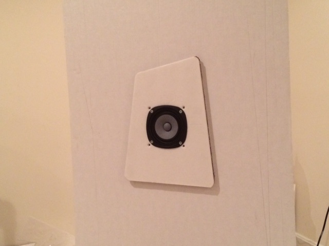
Agreed. Re-measuring in an IEC baffle is a waste of time as you will never use an IEC baffle as a speaker. They are huge. So big in fact, you can't even make one from a single. 4x8 sheet of plywood. The width is just over 4 ft! A much smaller trapezoidal test baffle fitted with a rear spiral tapered TL a la Nautilus will serve you well for characterizing drivers. The trapezoid reduces diffraction artifacts and the rear chamber simulates infinite size rear chamber like an IB. My measurements of a very practical (circa 12in x 9in) trapezoid baffle with a Nautaloss rear chamber match closely with a 2ft x 3ft open baffle.
It looks like an IEC baffle, which varies with driver size, produces some very familiar diffraction anomalies. You see that shape on boxed tweeter response a lot. But higher in frequency in your typical foot wide box, and can be even worse without an offset.
Attachments


Agreed. Re-measuring in an IEC baffle is a waste of time as you will never use an IEC baffle as a speaker. They are huge. So big in fact, you can't even make one from a single. 4x8 sheet of plywood. The width is just over 4 ft! A much smaller trapezoidal test baffle fitted with a rear spiral tapered TL a la Nautilus will serve you well for characterizing drivers. The trapezoid reduces diffraction artifacts and the rear chamber simulates infinite size rear chamber like an IB. My measurements of a very practical (circa 12in x 9in) trapezoid baffle with a Nautaloss rear chamber match closely with a 2ft x 3ft open baffle.
Sorry if I missed this but could you please provide a link to your testing of this, please?
Thanks
Small speakers suffer a lot from diffraction anomalies. AFAIK, most of the midrange peak with small speakers like the BBC LS3/5A requiring a notch filter around 1-1.5kHz is actually coming from the tiny baffle.
If you put the mid and tweeter near the inside edge, it all looks a lot better, and you can dispense with equalisation. Morgan Jones does it with his (below) beautiful Arpeggio Fullrange Speaker.
And Troels does it in his 3 Way Classic.
These are the right-hand speakers, of course. Two masters at the peak of their powers. Enjoy. 🙂
Attachments


Sorry if I missed this but could you please provide a link to your testing of this, please?
Thanks
Thread is here:
http://www.diyaudio.com/forums/full...parison-3in-4in-class-full-range-drivers.html
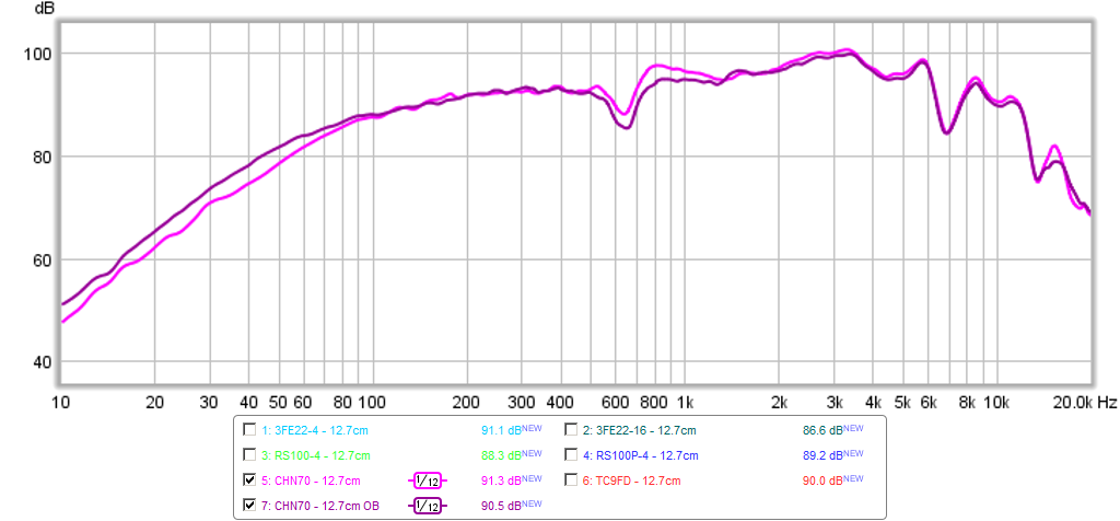
Here is trapezoid with OB around it. The OB did not change response appreciably from the trapezoid and Nautaloss rear chamber.
This is the graph:
- Status
- Not open for further replies.
- Home
- Loudspeakers
- Multi-Way
- iec baffles vs cabinet measurements